
mithomas - I'm preparing schematic with all voltages - handy for troubleshooting ;
don't despair - I'm grunschnabbel after all these years ........

don't despair - I'm grunschnabbel after all these years ........
Offset
Thanks 😀
Regarding offset
I have been able to get the VoltM DC readings down below .5volts or so with WR2, and .2 or .3v from V+ to V- using WR1 inside of circuit method.
These don't look like great numbers, and is always drifting a little.
But I can't get zero, so I don't know what's acceptable.
I would like to know what other have achieved here if you got the time. I am just shorting the inputs, so I dont know if it will behave better with a real volume pot, and sealed up better than my unfinished case.
At least I didn't blow all the fuses out...YET!
Re: Offset

that's good enough for Pumpie outa box .
now - you can make a box and , with all pcbs cooked inside , finish procedure .
mithomas said:Thanks 😀
Regarding offset
I have been able to get the VoltM DC readings down below .5volts or so with WR2, and .2 or .3v from V+ to V- using WR1 inside of circuit method.
These don't look like great numbers, and is always drifting a little.
But I can't get zero, so I don't know what's acceptable.
I would like to know what other have achieved here if you got the time. I am just shorting the inputs, so I dont know if it will behave better with a real volume pot, and sealed up better than my unfinished case.
At least I didn't blow all the fuses out...YET!
that's good enough for Pumpie outa box .
now - you can make a box and , with all pcbs cooked inside , finish procedure .
Re: Re: Offset
Sweet.
I am still nervous about the g to s voltage variance, but I will look for you data - it seems I am off on Q5 and Q7 pairs. I have been checking the nearby resistance figures, and look okay at a micro level.


Zen Mod said:
that's good enough for Pumpie outa box .
now - you can make a box and , with all pcbs cooked inside , finish procedure .
Sweet.
I am still nervous about the g to s voltage variance, but I will look for you data - it seems I am off on Q5 and Q7 pairs. I have been checking the nearby resistance figures, and look okay at a micro level.
Hey sweet guys.
Choky, manu, steeno, cviller and more...
Merry Christmas too all off you

Mrs. Magura😉
Choky, manu, steeno, cviller and more...
Merry Christmas too all off you
Mrs. Magura😉
Mrs.Magura said:Hey sweet guys.
Choky, manu, steeno, cviller and more...
Merry Christmas too all off you
Mrs. Magura😉
Attachments

Mrs.Magura said:Hey sweet guys.
Choky, manu, steeno, cviller and more...
Merry Christmas too all off you
Mrs. Magura😉
Thanks a lot, Mrs. Magura🙂

Merry Christmas to you

🙂
Mrs.Magura said:Hey sweet guys.
Choky, manu, steeno, cviller and more...
Merry Christmas too all off you
Mrs. Magura😉
Mrs Magura, Dear princess ...
Joyeux Noël et bonne et heureuse année...
🙂
Manu
Manu said:And Merry X-mas to all pooftaahs around here
See you next year

Sretan put !
(svuda prodji , kuci dodji 😉 )
kiss G.
Zen Mod said:
(svuda prodji , kuci dodji 😉 )
Sure ... 😉 thats the very aim of travel ...
In few hours I am entering the dark internet free zone ... french jungle ... scary ...

Manu
Hi all and merry Xmas,
just a quick Q. I've finished the test setup for the AX's and hooked them up to the pumpkin. This is where trouble starts. When hooking them up I get a rather large differential offset (0.7V) at the speakers. I've solved this for now by putting some caps on the input of the AX's.
This leads me to believe the output resistors to ground (R27&29)on the pumpking might be the culprit. Apart from better matching would it be possible to omit these or raise them to something like 1M to lessen the effect? Using two caps in series to block dc seems a bit unneccesary and I think and this would simplify things.
regards,
Joris
Oh and just in case: Folle Lok en Seine (have a lucky new year and blessing)
jazz said:............
This leads me to believe the output resistors to ground (R27&29)on the pumpking might be the culprit. ...............
Oh and just in case: Folle Lok en Seine (have a lucky new year and blessing)
😉
in that case - seems that your X don't like any resistance in front of gates , ie. series resistors to gates ;
you can freely leave R27 & R29 out , just be sure that Pumpie output caps are discharged when connecting cables to amp .
yup - Folle Lok en Seine .........
page 3? the horror!
anyways, I have a question for Pumpkin geniuses... no about Pumpkin of course. What is the effect of putting capacitance in parallel with feedback resistors? Is this some sort of compensation, and how does it effect gain reduction? I'd like to learn more!
anyways, I have a question for Pumpkin geniuses... no about Pumpkin of course. What is the effect of putting capacitance in parallel with feedback resistors? Is this some sort of compensation, and how does it effect gain reduction? I'd like to learn more!
Problem with Shunty and Pumpkin
Having some problems with my shunty and pumpkin & need help - it's a rather long read as it spans over several days.
1) After many moons - finally wired up my shunties and pumpkies.... ....
First turn on - 1 of the slow fuse on +V of shunty smoked and
blackened - LED off on that side
-V ok : -33V on testing - LED on (I'm using a 36-0-36 transformer)
Other shunty board ok
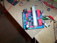
Took a quick check - noted C7a reversed polarity (see pic) - desolder
and put in correct position.
Repeat test - again +V side - fuse smoked and blew.
2) Days later -
Further check - found that Q2 Q11 & Q11a are not isolated from heat
sink despite plastic insulators. Rectified the issue.
Also discovered that the middle leg of Q11a is not connected to ground
- unlike the other shunty board - pads looked okay, pads also not
connected to ground, don't know what's the reason... ....
reconnected the middle leg of Q11a to GND (was
not grounded previously)
- restarted the machine and this time the fuse did not blow.
However was unable to adjust the -Vout and +Vout with WR1 on this
shunty board (the other shunty board is ok) -Vout remained 33.0V and
+Vout 33.8V (Vin is 46.6V, using a 36V-0-36V transformer). Heat sink
is also colder 33 degC compared to 45 degC on the other shunty board.
Any idea what's wrong?
Pumpkin Issues
- Went ahead and connected pumpkin to the shunty boards - 1 channel ok.
The other channel was unable to adjust to 0V the potential between
ground and channel using WR2, voltage remained at 2.0V (no change in
voltage when adjusting WR2), able to adjust to zero offset with WR1
though. Again what's the problem.
Was too impatient and connected the pumpkin to a cheap amp / speaker
and was able to get music out of it, without any static or noise.
Now all i need is to solve the remaining above issues.
thanks
her shann
Having some problems with my shunty and pumpkin & need help - it's a rather long read as it spans over several days.
1) After many moons - finally wired up my shunties and pumpkies.... ....
First turn on - 1 of the slow fuse on +V of shunty smoked and
blackened - LED off on that side
-V ok : -33V on testing - LED on (I'm using a 36-0-36 transformer)
Other shunty board ok
Took a quick check - noted C7a reversed polarity (see pic) - desolder
and put in correct position.
Repeat test - again +V side - fuse smoked and blew.
2) Days later -
Further check - found that Q2 Q11 & Q11a are not isolated from heat
sink despite plastic insulators. Rectified the issue.
Also discovered that the middle leg of Q11a is not connected to ground
- unlike the other shunty board - pads looked okay, pads also not
connected to ground, don't know what's the reason... ....
reconnected the middle leg of Q11a to GND (was
not grounded previously)
- restarted the machine and this time the fuse did not blow.
However was unable to adjust the -Vout and +Vout with WR1 on this
shunty board (the other shunty board is ok) -Vout remained 33.0V and
+Vout 33.8V (Vin is 46.6V, using a 36V-0-36V transformer). Heat sink
is also colder 33 degC compared to 45 degC on the other shunty board.
Any idea what's wrong?
Pumpkin Issues
- Went ahead and connected pumpkin to the shunty boards - 1 channel ok.
The other channel was unable to adjust to 0V the potential between
ground and channel using WR2, voltage remained at 2.0V (no change in
voltage when adjusting WR2), able to adjust to zero offset with WR1
though. Again what's the problem.
Was too impatient and connected the pumpkin to a cheap amp / speaker
and was able to get music out of it, without any static or noise.
Now all i need is to solve the remaining above issues.
thanks
her shann
- Home
- Amplifiers
- Pass Labs
- Pumpkin preamp - ordered by Steen , official making thread