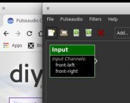
You don't. PaXoverRack will set it's input sink as default sink so it will work system wide with any pulseaudio enabled application. I highly recommend reading the online help, section "theory of operation" 😀
Request:
As I have no measurement microphone at the moment, can anybody provide me with a combination of real life woofer/tweeter or woofer/midrange/tweeter FRD measurement files for testing? I only found a database of woofers online...
As I have no measurement microphone at the moment, can anybody provide me with a combination of real life woofer/tweeter or woofer/midrange/tweeter FRD measurement files for testing? I only found a database of woofers online...
Look at the Monkey Coffin thread.
Open Source Monkey Box
There is more than this: check the thread after page 45. It will be interesting to see to what extent you will be able to model the filters and target curves for the Monkey Coffin in your programme.
Good Luck,
Eelco
Open Source Monkey Box
There is more than this: check the thread after page 45. It will be interesting to see to what extent you will be able to model the filters and target curves for the Monkey Coffin in your programme.
Good Luck,
Eelco
I got a Behringer ECM8000 or what ever it is. I'd gladly give it you. Whats postage cost to your neck of the woods?
I got a Behringer ECM8000 or what ever it is. I'd gladly give it you. Whats postage cost to your neck of the woods?
Very kind, gladly accept if postage is within reasonable range. Will PM you.
RFC!
To whet everybody's appetite and maybe to get some comments on the design...
I still need to do some research how to sum up the phase responses before I can release these features...
To whet everybody's appetite and maybe to get some comments on the design...
I still need to do some research how to sum up the phase responses before I can release these features...
Attachments
-
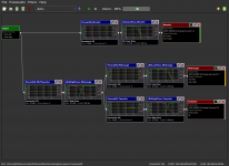 crossover_monkeybox.png163.4 KB · Views: 329
 -
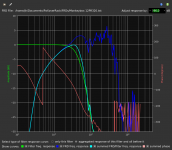 frd_dialog_woofer.png141.5 KB · Views: 328
 -
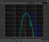 frd_dialog_midrange.png132.7 KB · Views: 320
 -
 frd_dialog_tweeter.png117.3 KB · Views: 322
 -
Monkeybox 12PR320.txt24.2 KB · Views: 90
-
MonkeyBox ScanR2904.txt20.7 KB · Views: 89
-
MonkeyBox VM752.txt23.8 KB · Views: 131
-
 global_frd_dialog.png97.2 KB · Views: 169
Amazing work you've done here - I just reactivated my account so I could follow along. I've been using a MiniDSP 2x8 for years and always wanted some sort of backup solution to my active XO in case the hardware gave up on me. This is absolutely perfect and what you've done in a relatively short period of time is very impressive. I've kept a couple old C2D tiny black boxes rolling along with WinXP and Linux flavors going just for such a project. Can't wait to get some free time and experiment with your app to see how it compares to the commercial alternative.
Thanks, let me know what you think, especially how it stacks up against a MiniDSP in terms of user friendliness...
General announcement: need to finish the online help section about working with FRD files, a release can be expected within the next few hours.
General announcement: need to finish the online help section about working with FRD files, a release can be expected within the next few hours.
I just released version 1.12 with the following changelog:
Regarding the missing calculation of phase shifts of delay filters I will have to first wrap my head around it...
Question for the experts: won't you have to measure the summed response anyways as the single driver measurements don't have timing information embedded into them, i.e. don't know about the driver<->microphone distance? Will probably be a lot smarter once I have a microphone available and can do some hands on testing...
Code:
pulseaudio-crossover-rack (1.12) stable; urgency=low
  * features:
    - added second order low-/highpass filters with variable Q
    - added dialog to load FRD frequency response files and look at the speaker
      response, both standalone and combined with the filter response
    - added dialog to show summed up responses of loaded FRD+filter responses
      plus their sums
      ATTENTION: This dialog does not yet account for phase shifts introduced
                 by delay filters, this is kind of complicated :/
    - changed all lower frequency parameter limits to 2Hz and all
      upper limits to 20kHz
    - made connection curves look nicer by using antialiasing
    - added dividers in EditFilterDialog to group parameters of ParamEq
    - added inverting filter
  * bugfixes:
    - insert/remove modules threw an error when no file was loaded
-- Jürgen Herrmann <t-5@t-5.eu> 2019-01-13
Regarding the missing calculation of phase shifts of delay filters I will have to first wrap my head around it...
Question for the experts: won't you have to measure the summed response anyways as the single driver measurements don't have timing information embedded into them, i.e. don't know about the driver<->microphone distance? Will probably be a lot smarter once I have a microphone available and can do some hands on testing...
Yes, the summed response will enable you to establish the relative distance, i.e. the distance between the acoustic centres of the drivers, a.k.a. the offset in the Z plane at the x/o frequency. That distance is not the same as the physical distance between the voicecoils of, say, a tweeter and a midwoofer.
In a conventional 25mm dome/16 cm midwoofer, the tweeter is located at Z=0 and the woofer some 30 mm behind that. I suppose for your software you have to convert the distance into milliseconds.
Good Luck and keep up the good work: I haven't tried it yet, but the GUI looks superb!
Eelco
In a conventional 25mm dome/16 cm midwoofer, the tweeter is located at Z=0 and the woofer some 30 mm behind that. I suppose for your software you have to convert the distance into milliseconds.
Good Luck and keep up the good work: I haven't tried it yet, but the GUI looks superb!
Eelco
How would you go about this when doing the measurements? Do you change the delay until you don't have dips in the summed response?Yes, the summed response will enable you to establish the relative distance, i.e. the distance between the acoustic centres of the drivers, a.k.a. the offset in the Z plane at the x/o frequency. That distance is not the same as the physical distance between the voicecoils of, say, a tweeter and a midwoofer.
In a conventional 25mm dome/16 cm midwoofer, the tweeter is located at Z=0 and the woofer some 30 mm behind that. I suppose for your software you have to convert the distance into milliseconds.
Thanks, very much appreciated 🙂Good Luck and keep up the good work: I haven't tried it yet, but the GUI looks superb!
Eelco
The delay is experimentally established in any x/o simulation program . First a measurement is made of the woofer separately without any crossover, then, without moving the microfone the tweeter is measured. Thirdly both drivers are simultaneusly measured without moving the mic. The non filtered summed curve will show a lot of valleys and peaks, but that is not problematic.
In the simulation program, LspCad 5.2 in my case, the summed curve of both drivers is overlaid with the combined measurement. This usually start with some discrepancies between both curves. After experimentally adding delay to the woofer in small steps, after some 30 mm or so both curves start to converge.
In the simulation program, LspCad 5.2 in my case, the summed curve of both drivers is overlaid with the combined measurement. This usually start with some discrepancies between both curves. After experimentally adding delay to the woofer in small steps, after some 30 mm or so both curves start to converge.
To be accurate also x and y placement of the drivers relative to each other must be defined.
You may want to take a look at VituiCad, XSim or Boxsim, all freeware.
You may want to take a look at VituiCad, XSim or Boxsim, all freeware.
So as far is I understand it the establishment of a correct delay between a pair of speakers is more the job of the speaker measurement software suite?! Actually I have some ideas already for such a program, but more on that once I have my mic and can do some initial testing. Of course it will then be tightly integrated with PaXoverRack and there will be no need to import/export FRD files anymore. Once i get going on this topic I will probably have another metric ton of questions but that shall be topic of another thread.
As far as I'm concerned I'm pretty happy with the state PaXoverRack is in right now, but we'll see how the new FRD feature is picked up by the audience that actually will use it... 😀
That's it for now folks, I'm off to bed 🙂
As far as I'm concerned I'm pretty happy with the state PaXoverRack is in right now, but we'll see how the new FRD feature is picked up by the audience that actually will use it... 😀
That's it for now folks, I'm off to bed 🙂
Last edited:
Well, the establishment of the correct delay is more a job of the x/o simulation and optimization software than the measurement software. So far, those jobs mostely have been been separated softwarewise - albeit with a few exceptions e.g. SoundEasy/LspCad- but there is no reason why the different jobs could not be integrated in one suite. Actually, that would be an excellent idea.
just a minor cleanup release:
Code:
pulseaudio-crossover-rack (1.13) stable; urgency=low
  * features:
    - delays now show the offset in millimeters
  * bugfixes:
    - removed formatter with 3 decimal places for float values (otherwise a
      precise delay value for example would be truncated)
    - removed some debug statements
    - reverted delay biquad filter coefficients to short form for
      performance reasons
-- Jürgen Herrmann <t-5@t-5.eu> 2019-01-14Sorry for the noise, but some improvements were in order 🙂
Code:
pulseaudio-crossover-rack (1.15) stable; urgency=medium
  * features:
    - added checkbox to ignore phase values in FRD files and replace them
      by calculated phase responses (minimum phase model, hilbert transform)
    - added checkbox to sync up the dB values by which FRD responses get
      shifted towards 0dB
    - added spinBox to manually shift phase responses. this enables exploration
      of different phase shifts needed to gain proper summation at crossover
      frequencies. phase shifts then have to be converted to delays in the
      crossover filter chain.
  * bugfixes:
    - switched internal data structures completely to complex representation
      of magnitude/phase responses. In the process a summation error was
      detected and fixed
-- Jürgen Herrmann <t-5@t-5.eu> 2019-01-15
pulseaudio-crossover-rack (1.17) stable; urgency=medium
  * bugfixes:
    - resized edit fields for filter parameters to accomodate new precision
-- Jürgen Herrmann <t-5@t-5.eu> 2019-01-15- Home
- Source & Line
- PC Based
- Pulseaudio Crossover Rack - multi-way crossover design & implementation with linux