Thanks for your response and the information. I don’t know much about the Williamson amp but the circuit I came across was in ‘Sound Practices’ magazine summer 1993 edition, page 11. The circuit title is ‘Original 1947 Williamson’ and it shows an amp with 2 x 6SN7GT plus 2 x 807 valves (tubes) + 5R4GY rectifier. The circuit has a reactor choke input followed by standard capacitor choke capacitor arrangement. There is also another smoother choke in the HT line to the 6SN7 valves.First of all, I don't know of any standard Williamson design that uses choke input. They all, to my knowledge, used cap input supplies. Can you point me to the design you saw?
The easiest way to build a Williamson power supply today is to use a Hammond 274BX power tranny and a 193D choke. With a 5AR4 rectifier tube this gets you exactly what you need for one channel of a Williamson. Power supply caps should be rated for at least 500VDC, preferably 600vdc+. You can then use a second choke like the original Williamson, or just a 150 ohm 5 watt resistor.
The output transformer is the sticky part. My top recommendation is a Heyboer S-265-Q Peerless copy. A really superb transformer. You have to call Heyboer and order them but right now they are way backlogged--I've been waiting on 8 pieces for quite while now. I would order 50% screen taps in case you want to do an "ultralinear" version. They're about $500 a pair with shipping.
After that it gets harder. Sowter is the only company I know of that currently makes a genuine Williamson OPT. You have to order them from England, if you can, and with shipping I calculated about $1000 for the pair. :-(
I have thought of contacting Electraprint and asking for a 10K p-p transformer, and asking if will handle 20dB of global feedback, but I haven't done so yet.
That leaves you with tracking down original Williamson OPT's. Acro TO-300's turn up on eBay fairly frequently and you can build a nice Heathkit W-3AM copy with those. Follow the feedback and tuning instructions in this thread:
https://audiokarma.org/forums/index.php?threads/a-new-beginning-heaths-w-3am.772780/
This is a very nice UL Williamson that will bring much pleasure.
Heathkit W-4's regularly turn up on eBay also and are worth restoring and fine tuning:
https://audiokarma.org/forums/index.php?threads/heathkit-w4-am-modifications.459630/
The W4 is not top-of-the-line but for what you pay for them they are a very nice amp, when rebuilt according to the above thread.
UTC LS-63's do turn up on eBay and will make a fine triode Williamson. The LS-57 can make a terrific triode EL-34 Williamson amp of 16wpc. That's what I'm using at the moment. You have to keep a search going on eBay for these.
Stancor A-8402's (triode only) and A-8407's (UL) turn up occasionally, but they pretty scarce now.
I have not tried any Hammonds in a Williamson circuit, though I plan to some time soon. I have a feeling they won't manage the amount of feedback required.
Everything else--Peerless, Partridge, Triad--are rare as hen's teeth.
Feel free to PM me, I might be able to think of some other options.
Hope this helps!
It caught my eye because I’ve experimented with smoother chokes recently in my Leak amps with very good results.
Having limited knowledge of transformers I tend to use the basic rule that the heavier the iron the better the performance.
Sowter here in the UK make a suitable one but the company has just been taken over and I think they are having production problems, it’s even difficult to get in touch with them at the moment.
I’ll have a look at the transformers you mention and check out availability. Thanks again
Cheers
Alan
I’ll try to post a picture of the above circuit
Attachments
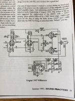
Thanks for your response and the information. I don’t know much about the Williamson amp but the circuit I came across was in ‘Sound Practices’ magazine summer 1993 edition, page 11. The circuit title is ‘Original 1947 Williamson’ and it shows an amp with 2 x 6SN7GT plus 2 x 807 valves (tubes) + 5R4GY rectifier. The circuit has a reactor choke input followed by standard capacitor choke capacitor arrangement. There is also another smoother choke in the HT line to the 6SN7 valves.
It caught my eye because I’ve experimented with smoother chokes recently in my Leak amps with very good results.
Having limited knowledge of transformers I tend to use the basic rule that the heavier the iron the better the performance.
Sowter here in the UK make a suitable one but the company has just been taken over and I think they are having production problems, it’s even difficult to get in touch with them at the moment.
I’ll have a look at the transformers you mention and check out availability. Thanks again
Cheers
Alan
I’ll try to post a picture of the above circuit
Ah, that's the "Radiotron" version by Langford Smith, adapted from the original Williamson to employ tubes available in Australia at the time. There's really no need for so much iron. Williamson used a single 10H choke for the main B+ and am second decoupling choke for the driver and input stages. 8 Henries is sufficient and the second choke is redundant, IMO. None of the later refinements to the Williamson employed it. I prefer to keep the power supply light and fast. The other thing I don't like about that design is that, lacking any bleeder resistor to maintain some sort of current draw, and in the event of circuit failure, you're looking at almost 800VDC sitting on the caps and tubes.
Too bad about Sowter. Since you're in the UK you'd be looking at a lot of expensive shipping for US transformers. eBay UK is showing a pair of original Partridge WWFB's right now for about what the Sowters cost. Perhaps you could make an offer. Then you've got the real deal! I also see some Acro TO-300s and TO290s on there. The TO-290 is 10K p-p with no screen taps and works very well, though those can be very hard to tame in the high frequency range. If you acquire a pair of those give me a jingle because I've worked with them and have some test results.
I'd also be happy to try to source something suitable from here in the US if you can't find anything there. Let me know if I can do anything more to help.
Yes the Partridge Output Transformers look very impressive, There could be additional import taxes to pay aswell, maybe 20%. I might keep an eye out for something similar here in the UK. Thanks for your help with this. Incidently aren't those bleeder resistor I can see fitted across the smoother caps ?
Yes the Partridge Output Transformers look very impressive, There could be additional import taxes to pay aswell, maybe 20%. I might keep an eye out for something similar here in the UK. Thanks for your help with this. Incidently aren't those bleeder resistor I can see fitted across the smoother caps ?
No, those are just for balancing the voltage across the caps. They don't draw any significant current. Depending on the input choke, you want to keep at least a 10-20mA load on the circuit at all times, IIRC.
I believe Majestic Transformes in Dorset UK will do this too. But please don't bother them for a couple of weeks till they ship my order ;-)Sowter is the only company I know of that currently makes a genuine Williamson OPT. You have to order them from England

do you know if the partridge txt has UL taps ?No, those are just for balancing the voltage across the caps. They don't draw any significant current. Depending on the input choke, you want to keep at least a 10-20mA load on the circuit at all times, IIRC.
Grounded metal is of no use against magnetic induced hum, not even steel. I tried it. The PT to OT radiation can be an issue only if they are side to side. PT stray magnetic field can be reduced by a copper flux band. I also found that shields on the input tubes have no effect at all. Keeping high impedance wires (where the connected parts are of high impedance) as short as possible is a good practice. E.g. from a 100k volume control to the input tube, or from anode of a pentode to the coupling capacitor and to the next grid.Just curious if mounting grounded metal or mu-metal plates are ever practiced in keeping AC electromagnetic fields from permeating other elements of an amp to minimize unwanted inductance, say, between PT"s and OT's or between power stages and input preamp stages.
do you know if the partridge txt has UL taps ?
No, they are triode only.
With No UL taps on a transformer, that means that depending on the other characteristics of the transformer,
and the circuit topology/architecture, the transformer still may be usable with:
Triodes
Tetrodes (True Tetrodes with no Suppressor Grid, and no Beam Formers)
Pentodes
Triode wired Pentodes
Beam Power tubes
Triode wired Beam Power tubes
Restricting to only Triodes is ignoring the capability of many transformers that do not have any UL tap(s).
If you doubt that, then send me your Partridge txt, and I will use them, and publish it.
By the way, there are several threads of circuits at Valves / Tubes that do use output tubes in UL, even though the output transformer does not have UL tap(s).
Just Saying . . .
Just to play devil’s advocate and test ideas - re comments on the merits of a light and fast PSU Using a motoring analogy I like to think of the acoustic gradient (say bass slam and treble crash) as the steep hill and the PSU (good regulation and smoothing) as the engine trying the climb it. The greater the power from the engine the less you will notice the hill ?Ah, that's the "Radiotron" version by Langford Smith, adapted from the original Williamson to employ tubes available in Australia at the time. There's really no need for so much iron. Williamson used a single 10H choke for the main B+ and am second decoupling choke for the driver and input stages. 8 Henries is sufficient and the second choke is redundant, IMO. None of the later refinements to the Williamson employed it. I prefer to keep the power supply light and fast. The other thing I don't like about that design is that, lacking any bleeder resistor to maintain some sort of current draw, and in the event of circuit failure, you're looking at almost 800VDC sitting on the caps and tubes.
Too bad about Sowter. Since you're in the UK you'd be looking at a lot of expensive shipping for US transformers. eBay UK is showing a pair of original Partridge WWFB's right now for about what the Sowters cost. Perhaps you could make an offer. Then you've got the real deal! I also see some Acro TO-300s and TO290s on there. The TO-290 is 10K p-p with no screen taps and works very well, though those can be very hard to tame in the high frequency range. If you acquire a pair of those give me a jingle because I've worked with them and have some test results.
I'd also be happy to try to source something suitable from here in the US if you can't find anything there. Let me know if I can do anything more to help.
This is a fantastic reply! Could you add anything to “proper angular orientation of all the magnetics” please?Planning to reduce the level of hum in a new design:
Do not use a magnetic steel chassis
Eliminate/shorten the RCA input connector ground loop (make it local).
Eliminate/shorten the B+ ground loop (make it local).
Properly use the 3-wire IEC power cord and IEC input connector, including a connection from ground to the chassis; A central ground point and chassis connection (that does not include the input local ground loop, and does not include the B+ local ground loop); and DC filament supplies for all DHT.
Lots of spacing and proper angular orientation of all the magnetics (power transformer, choke, output transformer, interstage transformer, and input transformer).
I shoot for much less than 1mV of hum at the loaded output secondary.
I designed 3 amplifiers with less than 100uV hum, designed one amplifier with 500uV hum (magnetic steel chassis), and my new design that I expect to have less than 100uV hum.
All my designs use 3 wire power mains, 3 wire power cord, and 3 IEC connector on the power amplifier.
All of them connect the power mains ground to the chassis. Safety First! Prevent the "Surviving Spouse Syndrome."
All of my signal sources use 2 wire power cords, some have a larger lug (hot). All the signal sources are commercial un-modified products.
If you do not know how to eliminate/shorten a specific kind of ground loop, tell me which kind of ground loop that you are trying to eliminate/reduce the hum.
A wire is both a resistor, and an inductor.
"Grounds are Commonly Mis-Understood" That is both true, and is a pun.
Lots of current and a little resistance creates lots of ground loop "signal"
A high frequency at low current, and a little inductance creates lots of ground loop "signal"
B+ Choke input filters create smooth low frequency hum, and smooth low frequency magnetic fields. These get into the ground loops; and into other 'magnetic' parts.
B+ Capacitor input filters create both low frequency hum and high frequency noise. These get into the ground loops.
A 200mA peak rectifier current into an input cap, creates a very large low frequency and high frequency magnetic field.
Even a short ground loop is still a single loop 'primary' winding of an Air transformer. Another loop that is nearby can pick up that, and will be a hum and noise signal to that other circuit.
Most ears are more sensitive to the harmonics of hum, than they are to the fundamental of the hum (as an example, coming from a B+ supply).
I am working on a new DHT build while still unsettled about ~8mv hum on my AC DHT build. My build follows a common anrrangement observed on similar amps where the PT and OPTs are at 90°. But in this arrangement the direction of the leakage from the PT is still pointed towards the OPTs. Excluding other components, would it be better to rotate both PT & OPTs 90° so that the PT leakage axis is not directed towards OPTs in addition to the axis of both items being perpendicular?
Sorry to reopen an old thread. The quoted post was so good though!
The common arrangement I referenced:
Last edited:
Beautiful amplifiers!
Think of transformers and chokes as having a coil that has an axis of magnetic field through the middle.
Keep those axis at right angles.
Only if one device axis is vertical, and the other two devices axis are horizontal, you can have all 3 rotated 90 degrees apart.
But in some cases, you have to orient the output transformer one way; yet have to orient both the power transformer and the choke the, but both the choke and power transformer at least can be 90 degrees versus the output transformers axis.
With potted transformers, potted B+ chokes, and potted output transformers, you can not 'See' the orientation of the coils under the potting enclosures.
So, you have to drive one potted device with AC, and measure the signal that is magnetically coupled to the other potted device.
You have to rotate them to find the worst coupling, then rotate (usually 90 degrees) to reduce the coupling.
Spacing them further apart helps, and reminder, do not use magnetic steel chassis.
Single ended output transformers and B+ chokes both have air gapped laminations. They have the highest degree of magnetic coupling.
I love, and use true choke input B+ filters (LCRCRC). The magnetic spray from them is greater than capacitor input B+ filters (CLCRC);
So watch out for those chokes to couple more to a single ended output transformer.
Push pull output transformers, and power transformers do not have air gaps, their E and I laminations are stacked in an interleaved manner
(A poor graphic illustration: E, I, 3, I, E, I, 3, I . . . . ). So the magnetic coupling is usually less.
I think your power transformer is the one that is not potted, Right?
There are many possible causes of 8mV hum for DHT. Assuming a good hum balance circuit, there still is/are:
Ground loops, B+ ripple, magnetic devices coupling, and ** output tube filament / plate non-perfect 'rotation', and non-symmetrical spacing.
Some tubes ** are better than others, even of the same manufacturer; or different manufacturer.
Last edited:
Thanks 6A3sUMMER! My amps are not quite as beautiful, credit to JELabs.
My amp is a somewhat similar SE 300b, with a similar non-potted Hammond PT. From some videos it seems the axis of these PT is pointed towards the OPT, while still at 90º. Is it that a perfect 90º would repel and so it doesn't matter at which device the two axis' meet? Or of the two possibilities, excluding other circuitry, there right option would be better for hum?

For my 8mV hum - from smartphone octave scan app it is mostly 120hZ. I have spent a lot of time experimenting (self-taught without a scope) the causes you mentioned: played with ground meeting points, separated a star of ground to chassis points, adding more capacitance, more inductance, different tubes. Not much change other than slight decrease when more capacitance AND inductance added. You are right ** I did find it to be higher with my more expensive yet better sounding tubes.
So much investigating the above that I overlooked the chassis being steel til now. 🤦 A different steel build with 2A3 is less so maybe why I did not consider the chassis material.
Is magnetic coupling hum 60 or 120 hZ?
My amp is a somewhat similar SE 300b, with a similar non-potted Hammond PT. From some videos it seems the axis of these PT is pointed towards the OPT, while still at 90º. Is it that a perfect 90º would repel and so it doesn't matter at which device the two axis' meet? Or of the two possibilities, excluding other circuitry, there right option would be better for hum?
For my 8mV hum - from smartphone octave scan app it is mostly 120hZ. I have spent a lot of time experimenting (self-taught without a scope) the causes you mentioned: played with ground meeting points, separated a star of ground to chassis points, adding more capacitance, more inductance, different tubes. Not much change other than slight decrease when more capacitance AND inductance added. You are right ** I did find it to be higher with my more expensive yet better sounding tubes.
So much investigating the above that I overlooked the chassis being steel til now. 🤦 A different steel build with 2A3 is less so maybe why I did not consider the chassis material.
Is magnetic coupling hum 60 or 120 hZ?
Last edited:
I suggest you take a look at these videos. I think the first one is the most instructive, but all are interesting. Do remember which way the winding are oriented in your transformers.
Simon
Simon
1. When I said Axis, I meant a straight line that goes through the coil windings of a transformer or choke.
Consider a coil, represented by a circle drawn like this: O
The axis points up toward you through the O, and down through the O away from you.
Post # 34 left picture, left magnetic device:
The coil is wound from West to Up, UP to East, East to Down, Down to West (one turn, now repeat for many turns).
Think of this coil as a Tire on a wheel.
The choke or transformer Axle (Axis) points North to South.
The Axis, in this case North to South, is the major magnetic field direction.
2. On a steel chassis, the magnetic fields are conducted all over the chassis. Because it goes everywhere, it can "twist" according to the magnetic field sources, and the chassis shape and dimensions.
The frequency of the hum is predominantly according to the magnetic source device:
Power Transformer mains frequency, 50Hz / 60Hz is dominant
B+ Filter Choke (full wave rectification), 2 X power mains frequency; 100Hz / 120 Hz is dominant.
With equal amounts of hum, generally:
50Hz / 60Hz; versus 100Hz / 120 Hz; . . . our ears tend to be more sensitive to the 100Hz / 120 Hz hum.
Thanks for clarifying. I understand. I'm only left wondering if there is any difference in the below options. Both options keep the axis at 90º

As far as I know, as long as the spacing from one set of laminations to the other set of laminations is the same . . .
there should be no difference on an aluminum chassis.
Perhaps a magnetic chassis skews the magnetic fields and makes a difference between the two orientation examples (often the laminations dimensions differ, one a square, and one a rectangle.
I have seen some working solutions where one set of laminations was rotated more like 30 Degrees to 50 degrees relative to the other set of laminations.
Only by driving one device, and measuring the output of the other device, and rotating one of them, will you be able to pre-determine the outcome before they are permanently mounted.
Don't forget, if you use a single ended output transformer, a choke (especially when in a LCRC filter), and a power transformer . . .
you will have 3 devices to orient versus each other. Push pull output transformers are less sensitive to magnetic fields than single ended output transformers.
When I had to use an existing magnetic steel chassis, I sometimes mount the magnetics away from the chassis . . .
I used 1/4 inch tall aluminum washers between the chassis and the choke or transformer mounting tabs, and used non magnetic screws to mount it.
I did this to possibly reduce the magnetically induced hum, but I never tested the difference (with and without the spacing and non-magnetic screws), so I do not know if it makes a difference or not.
The laminations are now spaced above the steel chassis by 1/4 inch. If this makes a difference, then there will be an additional improvement of
6dB more hum reduction if the spacing is 1/2 inch (square law of the distance, d).
Of course, this spacing looks kind of silly.
The other reason I like aluminum chassis, is that I usually use the hand drill my Dad gave me when I was 5 years old.
Steel is too hard to drill that way.
Last edited:
Really appreciate your help and thorough explanation. I'm new and learning things through investigation of said 8mV hum.
Through your help I can believe my chassis layout is fine, even including the choke. Well, the best it can be without more space / rotating vertical axis as well. I am not bound to steel chassis and will happily start using aluminum now understanding some benefits.
I think my hum is mostly 120hZ and due to AC on DHT. Still I am curious and will change the chassis to aluminum and see if anything changes.
Without a complete and accurate schematic of your amplifier, it is hard to troubleshoot hum.
Here is one idea that may work, depending on your circuit topology.
Simple test:
If the output tube is self biased; and if the driver tube plate is RC coupled through a capacitor to the output tube grid (with an output tube Rg to ground; that is the form of RC coupling), then you can short across the Rg resistor. Test to see if that reduces the hum.
If the hum is still 8 mV, than it is caused by:
1. The AC filament operated DHT output tube,
2. The magnetic fields of the choke or power transformer that are coupling to the output transformer,
3. It is the ripple of the B+ that feeds the output stage.
Most of, but not all, hum that is caused by AC heating of a DHT, can be cancelled by using a hum balance pot and associated circuit.
Are you using a good hum balance circuit?
B+ ripple and single ended stage.
Example: A 300B (plate impedance, rp = 700 Ohms), and an output transformer 3500 Ohms to 8 Ohms.
3500 to 8 Ohms is 20.9 to one turns ratio (and 20.9 to 8 Ohms voltage ratio).
B+ ripple is divided between 3500 Ohms and 700 Ohms (3500 / (3500 + 700)) = 3500/4200 = 0.833
If all the 8mV ripple is caused by B+ ripple, we have:
8mV x (20.9 / 0.833) = 8mV x (25.1) = 200.8mV B+ ripple.
200mV B+ ripple can cause 8mV ripple, if the output tube is a 300B, and the output transformer is 3500 Ohm to 8 Ohm.
What is your output tube type?
What is your output transformer primary impedance?
What is your output transformer secondary impedance?
How much B+ ripple voltage is at the output transformer primary?
. . . See how that works?
Last edited:
- Home
- Amplifiers
- Tubes / Valves
- PT and OT in close proximity