Hello and thanks for stopping by.
Just curious if mounting grounded metal or mu-metal plates are ever practiced in keeping AC electromagnetic fields from permeating other elements of an amp to minimize unwanted inductance, say, between PT"s and OT's or between power stages and input preamp stages.
Where I understand that proper layout is the best and first line of practical defense for AC induction, is this ever used to successfully address those issues? And are there other issues that can arise from attempting to do this?
Thanks!
Best,
Phil Donovan
Usually if the mains transformer is placed at 90° to the output transformers, that is all that is required.
If it is good enough for Quad, it's good enough for the rest I say.
If it is good enough for Quad, it's good enough for the rest I say.
Thanks Jon, And I will take heed to that during layout and testing.
What's happening is that I'm gearing up for a stereo tube amp, PP UL pair of KT88 and pair of 6SN7's for each channel (probably). I do already have a particular PT that suits the requirements of one side/channel and considering just buying another one of equal specs so that each channel would have its own PT. This would save some money (less battles to have to win) plus make experimenting with a single channel at home before the build more immediately feasible. The advantage I though this would have also is that it is being built on a 19" rackmount box/chassis that is open to whatever depth is sufficient for some reasonable spread between components and area's. Where this is only my 3rd amp build, I'm not feeling experienced enough to prophesize issues should they, or if they come up. So far my amp builds have been quiet as can be but if this were to have 2 PT's then I may be increasing the potential for EM ac induced hum/noise. I pay attention to layout and wiring dressing as much as I can, digging for all the rules that guide.
Just planning for any hum issues if all my trials don't fully succeed. I worry like that somethings.
Thanks!
Best,
Phil
Planning to reduce the level of hum in a new design:
Do not use a magnetic steel chassis
Eliminate/shorten the RCA input connector ground loop (make it local).
Eliminate/shorten the B+ ground loop (make it local).
Properly use the 3-wire IEC power cord and IEC input connector, including a connection from ground to the chassis; A central ground point and chassis connection (that does not include the input local ground loop, and does not include the B+ local ground loop); and DC filament supplies for all DHT.
Lots of spacing and proper angular orientation of all the magnetics (power transformer, choke, output transformer, interstage transformer, and input transformer).
I shoot for much less than 1mV of hum at the loaded output secondary.
I designed 3 amplifiers with less than 100uV hum, designed one amplifier with 500uV hum (magnetic steel chassis), and my new design that I expect to have less than 100uV hum.
All my designs use 3 wire power mains, 3 wire power cord, and 3 IEC connector on the power amplifier.
All of them connect the power mains ground to the chassis. Safety First! Prevent the "Surviving Spouse Syndrome."
All of my signal sources use 2 wire power cords, some have a larger lug (hot). All the signal sources are commercial un-modified products.
If you do not know how to eliminate/shorten a specific kind of ground loop, tell me which kind of ground loop that you are trying to eliminate/reduce the hum.
A wire is both a resistor, and an inductor.
"Grounds are Commonly Mis-Understood" That is both true, and is a pun.
Lots of current and a little resistance creates lots of ground loop "signal"
A high frequency at low current, and a little inductance creates lots of ground loop "signal"
B+ Choke input filters create smooth low frequency hum, and smooth low frequency magnetic fields. These get into the ground loops; and into other 'magnetic' parts.
B+ Capacitor input filters create both low frequency hum and high frequency noise. These get into the ground loops.
A 200mA peak rectifier current into an input cap, creates a very large low frequency and high frequency magnetic field.
Even a short ground loop is still a single loop 'primary' winding of an Air transformer. Another loop that is nearby can pick up that, and will be a hum and noise signal to that other circuit.
Most ears are more sensitive to the harmonics of hum, than they are to the fundamental of the hum (as an example, coming from a B+ supply).
Last edited:

Thanks Jon, And I will take heed to that during layout and testing.
What's happening is that I'm gearing up for a stereo tube amp, PP UL pair of KT88 and pair of 6SN7's for each channel (probably). I do already have a particular PT that suits the requirements of one side/channel and considering just buying another one of equal specs so that each channel would have its own PT. This would save some money (less battles to have to win) plus make experimenting with a single channel at home before the build more immediately feasible. The advantage I though this would have also is that it is being built on a 19" rackmount box/chassis that is open to whatever depth is sufficient for some reasonable spread between components and area's. Where this is only my 3rd amp build, I'm not feeling experienced enough to prophesize issues should they, or if they come up. So far my amp builds have been quiet as can be but if this were to have 2 PT's then I may be increasing the potential for EM ac induced hum/noise. I pay attention to layout and wiring dressing as much as I can, digging for all the rules that guide.
Just planning for any hum issues if all my trials don't fully succeed. I worry like that somethings.
Thanks!
Best,
Phil
Sounds suspiciously like a Williamson. ;-) Can you tell us more about then project? I have a lot of experience building Williamsons. They're not terribly fussy about noise--stability, yes, but I've never had noise problems.
I'll be back because I'm off to bed but yes, it is a Williamson. And actually this amp is not for reproduction of recorded music. It is for a fretless Ebow electric guitar that I built that I have found benefits more from a cleaner audio amplification pathway than through my Fender and Marshall type guitar amps. I usually play it through a Seventh Circle DI module, into a preamp, mostly my N72 Neve preamp, maybe into my D16 DBX like compressor and finally into a stereo processor like my Kurzweil Rumour. I wanted a playback system that was rather hi fi, stereo, but hopefully powerful enough for small stages and little venues, you know, coffee shop type things with other acoustic instruments. The other part of this project is to put together a couple of hi fi type speakers with high power fairly full range speakers, well, enough to cover around 80 to 10kHz or so. I did begin to start seeing a number of comments about the Williamson and stability, I assume that is referring to it breaking into oscillations under certain conditions. I heard that there is a Mullard design that is purportedly better in that regard and perhaps I will try that also. I have a little tube am design station I made up that would at least allow me to hear one channel to compare and decide which one I think is serving the fretless Ebow guitar the best. Thank everyone for inputting here. Its nigh nigh time and I'll come back tomorrow. Thanks and Best,
Phil D.
Phil D.
The Williamson, IMO, produces a wonderful, natural sound for hi-fi applications. I'm a bit fanatical about it. ;-) But it does pose issues and needs to be carefully built, with the right ouput transformer and expert tuning, to avoid stability issues. For your purposes, a Mullard design might be easier to implement. However, in either case, transformer placement and orientation shouldn't be too much of a problem. I've built a dozen line-level Williamson tube power amps without overly concerning myself about induced transformer noise.I'll be back because I'm off to bed but yes, it is a Williamson. And actually this amp is not for reproduction of recorded music. It is for a fretless Ebow electric guitar that I built that I have found benefits more from a cleaner audio amplification pathway than through my Fender and Marshall type guitar amps. I usually play it through a Seventh Circle DI module, into a preamp, mostly my N72 Neve preamp, maybe into my D16 DBX like compressor and finally into a stereo processor like my Kurzweil Rumour. I wanted a playback system that was rather hi fi, stereo, but hopefully powerful enough for small stages and little venues, you know, coffee shop type things with other acoustic instruments. The other part of this project is to put together a couple of hi fi type speakers with high power fairly full range speakers, well, enough to cover around 80 to 10kHz or so. I did begin to start seeing a number of comments about the Williamson and stability, I assume that is referring to it breaking into oscillations under certain conditions. I heard that there is a Mullard design that is purportedly better in that regard and perhaps I will try that also. I have a little tube am design station I made up that would at least allow me to hear one channel to compare and decide which one I think is serving the fretless Ebow guitar the best. Thank everyone for inputting here. Its nigh nigh time and I'll come back tomorrow. Thanks and Best,
Phil D.
Thanks for responding.
I am very interested in setting up a channel of the Williamson and seeing (hearing) how it performs. (Hell, already made an order to Digikey for some of the components for it).
A couple of question if you don't mind - When you mention the right OT, is that referring to a well determined primary impedance? or are there other considerations that go into choosing the right OT?
What other aspects of these amps call for expert tuning? Being that this will be my first hi fi amp, is this something I will be able to accomplish with what I have for test equipment? (Scope, DMM's, signal generators).
I noticed on the particular schematic I have that the NFB is coming of a tap and going to only the cathode of the 1st gain stage. For my application, I can probably get away with having more non-linearity since this amp doesn't have to be completely about accurate reproduction, its as much about being a tonal generator for an odd duck instrument. If using less NFB will help stability issues that is certainly something that can be played with.
Again, thanks for your valuable input here, I'm rather excited about this phase of the journey. I've had 2 very successful guitar amp builds so, I'm looking forward to the new topology here!
Best,
Phil D.
https://i.pinimg.com/564x/c2/ef/91/c2ef919d618c7faa2da4434df889d70b.jpg
Or, this one, almost same I think, maybe identical
https://www.google.com/imgres?imgur...hUKEwjLjtTbm4D2AhWLn3IEHbwTCuwQMygEegUIARCAAg
This should be the link(s) to the schematic I was looking at. hope it works.
Best,
Phil D
Or, this one, almost same I think, maybe identical
https://www.google.com/imgres?imgur...hUKEwjLjtTbm4D2AhWLn3IEHbwTCuwQMygEegUIARCAAg
This should be the link(s) to the schematic I was looking at. hope it works.
Best,
Phil D
I can add some learnt lessons to Mr Summers comments.
90deg PT on OPT are fine even if next to each other.
Use insulated RCA connectors and take the screen grounds to the input stage. Make sure the input stages are next to each other so you don't create a differential ground current through the loop formed by the input cables.
Try and separate mains each from 0V with say 15R between them. If you don't want to do this consider a pseudo differential input.
Avoid placing the input stage over the PT!
Maybe DC for heaters but if not use a separate transformer for the first stage (and drivers if you wish) heater so it does not pick up rectifier buzz from the HT rectifiers and through the heater supply. Don't make the grid impedances to high here.
Thanks for responding.
I am very interested in setting up a channel of the Williamson and seeing (hearing) how it performs. (Hell, already made an order to Digikey for some of the components for it).
A couple of question if you don't mind - When you mention the right OT, is that referring to a well determined primary impedance? or are there other considerations that go into choosing the right OT?
What other aspects of these amps call for expert tuning? Being that this will be my first hi fi amp, is this something I will be able to accomplish with what I have for test equipment? (Scope, DMM's, signal generators).
I noticed on the particular schematic I have that the NFB is coming of a tap and going to only the cathode of the 1st gain stage. For my application, I can probably get away with having more non-linearity since this amp doesn't have to be completely about accurate reproduction, its as much about being a tonal generator for an odd duck instrument. If using less NFB will help stability issues that is certainly something that can be played with.
Again, thanks for your valuable input here, I'm rather excited about this phase of the journey. I've had 2 very successful guitar amp builds so, I'm looking forward to the new topology here!
Best,
Phil D.
When I say the "right" output transformer, I mean one with enough bandwidth to tolerate the amount of feedback you are applying. I have only built Williamsons with vintage transformers made for such amplifiers, like UTC, Peerless, Stancor, Acrosound, etc. I have never tried a Hammond or Edcor, though most DIYers seem leery that these have the proper specs for the job. Someday soon I hope to try some new models and see how they perform.
Given your application, you could reduce the feedback and perhaps avoid instability. With the original triode Williamson, the main problem was ultrasonic oscillation, which was partially solved by the addition of a low-pass filter in the first stage. The second thing that helps here is a phase-lead cap across the feedback resistor to increase the high-frequency phase margin and improve stability. With a pentode or ultralinear Williamson, low-frequency issues arise, so designer like Haffler and Keroes, who mpinoeered the ultralinear design, changed the coupling cap values to provide better LF stability.
Here's an excellent thread from Audiokarma that gives you an idea of how to stabilize a vintage Williamson, and what to look for when measuring it:
https://audiokarma.org/forums/index.php?threads/regilding-the-gilded-lily-heaths-w-2m.767851/
Last edited:
https://i.pinimg.com/564x/c2/ef/91/c2ef919d618c7faa2da4434df889d70b.jpg
Or, this one, almost same I think, maybe identical
https://www.google.com/imgres?imgur...hUKEwjLjtTbm4D2AhWLn3IEHbwTCuwQMygEegUIARCAAg
This should be the link(s) to the schematic I was looking at. hope it works.
Best,
Phil D
Both of these are standard fixed-bias Williamsons. Note that neither design has any stabilizing features, like a low-pass ("shelf") network across the first plate resistor, or a phase-lead cap across the feedback resistor. If they were really built this way there would definitely be stability issues.
If you don't need 50 wpc you could go with cathode bias, for 35 wpc, which would be easier to build.
One transformer that would work for your purposes would be a Dynaco A-431. The reissues from Dynakit Parts are very good but have been out of stock for quite a while, so they may be hard to find at the moment.
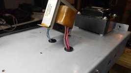
Attached is a pic of a Fender Blues Jr. guitar amp output and power transformer mounting arrangement. As can be seen they are at 90 degrees to each other. These amps have a low level hum present on the output even with all the gain controls set to minimum. Same thing if all the tubes are removed. If a piece of magnetic shielding sheet steel is placed at an angle between the transformers the hum can be nulled to almost nothing. The magnetic shielding is sometimes used to mod amps that will be used for recording. The low level hum doesn't matter for live performance.
Attachments
Hi Mark,
On my first tube amp build (Rob Robinette Fender Vibroverb normal channel around 40 watts) I Placed the PT in the corner of the chassis furthest away from the input "corner" then hooked a set of headphones up to the 16 ohm tap on the OT, powered up the PT (no loads, wire ends shrink tubed) and spun the OT all around the top of the chassis to listen for the hum at various angles and distances. As suspected, the most quiet was all the way across the shorter Princeton reverb chassis but, I managed to find an angle and distance a little further than half way that significantly minimized the hum to near inaudibility in the headphones. If you look at the amp, you would think someone very drunk took the job of layout but, that was it. It got the OT also very close to where I wanted the speaker out put jacks and reasonable far away from anything that could be effected by it. That was an eye opener - really got to see the composite results of distance and angle. Also, I shimmied around the choke in between them, and even the physical presence of that had a small bearing on the level and/or texture of the hum).
It is good to know though that the issue can be addressed by placing metal panels between things as a last resort kind of thing, not that I'd ever want to rely on that as a layout technique!
Thank for that,
Phil D.
Hi Grover,
And yes, those are the unmodified schematics as Williamson designed, and from what I heard, shortly after admitted "yeah, that wasn't quite it". So I will be looking to update things as needed, including what you have described, and see how this plays out. Maybe I will try cathode bias if not even for curiosity. If I thought there was still enough practical power and that the tone was still as desirable then might keep it that way. This is all partly learning experience too, I'm very interested in what the outcomes are of various acceptable modifications can make, as well as wanting this amp to be a performer.
Thanks for your valuable recommendations and I'm sure I'll be plugging to get the specifics on what I'm doing and the technical understanding of what is involved.
And I have had my eye on those Dynaco replacement transformers at Triad for a long time. I get the feeling of high quality about those from everything I've heard. Where they are more expensive it would be a bit more difficult to justify the extra cost but we'll see. My Beatles tribute band makes a lot of extra cash in the summer so, that's some leverage!
Thank you!
Best,
Phil Donovan
That Gilded-Lily article is a real read-through, very detailed. I'll be digesting that for a while! But obviously much was considered in that article to help move the Williamson toward greater stability. Looks like a great education exercise as well as bringing those amps to a better place. Awesome, thanks,
Best,
Phil Donovan
Best,
Phil Donovan
Hello, I saw an old williamson circuit and was very impressed by the power supply (choke input followed by capacitor/choke Pi network) I am thinking of building a williamson amp, what output transformer would you recommend ?The Williamson, IMO, produces a wonderful, natural sound for hi-fi applications. I'm a bit fanatical about it. ;-) But it does pose issues and needs to be carefully built, with the right ouput transformer and expert tuning, to avoid stability issues. For your purposes, a Mullard design might be easier to implement. However, in either case, transformer placement and orientation shouldn't be too much of a problem. I've built a dozen line-level Williamson tube power amps without overly concerning myself about induced transformer noise.
Hello, I saw an old williamson circuit and was very impressed by the power supply (choke input followed by capacitor/choke Pi network) I am thinking of building a williamson amp, what output transformer would you recommend ?
First of all, I don't know of any standard Williamson design that uses choke input. They all, to my knowledge, used cap input supplies. Can you point me to the design you saw?
The easiest way to build a Williamson power supply today is to use a Hammond 274BX power tranny and a 193D choke. With a 5AR4 rectifier tube this gets you exactly what you need for one channel of a Williamson. Power supply caps should be rated for at least 500VDC, preferably 600vdc+. You can then use a second choke like the original Williamson, or just a 150 ohm 5 watt resistor.
The output transformer is the sticky part. My top recommendation is a Heyboer S-265-Q Peerless copy. A really superb transformer. You have to call Heyboer and order them but right now they are way backlogged--I've been waiting on 8 pieces for quite while now. I would order 50% screen taps in case you want to do an "ultralinear" version. They're about $500 a pair with shipping.
After that it gets harder. Sowter is the only company I know of that currently makes a genuine Williamson OPT. You have to order them from England, if you can, and with shipping I calculated about $1000 for the pair. :-(
I have thought of contacting Electraprint and asking for a 10K p-p transformer, and asking if will handle 20dB of global feedback, but I haven't done so yet.
That leaves you with tracking down original Williamson OPT's. Acro TO-300's turn up on eBay fairly frequently and you can build a nice Heathkit W-3AM copy with those. Follow the feedback and tuning instructions in this thread:
https://audiokarma.org/forums/index.php?threads/a-new-beginning-heaths-w-3am.772780/
This is a very nice UL Williamson that will bring much pleasure.
Heathkit W-4's regularly turn up on eBay also and are worth restoring and fine tuning:
https://audiokarma.org/forums/index.php?threads/heathkit-w4-am-modifications.459630/
The W4 is not top-of-the-line but for what you pay for them they are a very nice amp, when rebuilt according to the above thread.
UTC LS-63's do turn up on eBay and will make a fine triode Williamson. The LS-57 can make a terrific triode EL-34 Williamson amp of 16wpc. That's what I'm using at the moment. You have to keep a search going on eBay for these.
Stancor A-8402's (triode only) and A-8407's (UL) turn up occasionally, but they pretty scarce now.
I have not tried any Hammonds in a Williamson circuit, though I plan to some time soon. I have a feeling they won't manage the amount of feedback required.
Everything else--Peerless, Partridge, Triad--are rare as hen's teeth.
Feel free to PM me, I might be able to think of some other options.
Hope this helps!
- Home
- Amplifiers
- Tubes / Valves
- PT and OT in close proximity