I've been playing around with both some real components and some circuit sims and I think I have a working concept for a wireless active "digital loudspeaker" based on the MiniDSP 2x4-crossover and MiniDIGI boards (one of each per speaker). This includes:
So, how to do this as a DIYer? Here's what I have come up with:
I have tested the concept using an inexpensive AV sender set to send the digital signal and this works well so I'd like to move on with the build.
Are there other here that might be interested in this kind of project? If so I can eventually design some PCBs for the control circuitry.
-Charlie
- S/PDIF digital audio sent wirelessly to the loudspeakers
- Remote digital volume control
- remote shutdown and power-up of most of the electronics in the loudspeaker (the control circuitry in the loudspeaker must remain powered up for this to work)
So, how to do this as a DIYer? Here's what I have come up with:
- Use an inexpensive "AV Sender" set consisting of one transmitter and two receivers. There is one receiver in each loudspeaker.
- The digital audio signal is sent over the "video" channel of the AV Sender in S/PDIF format.
- Analog circuitry is used to send other control signals via the L and R audio channels of the AV sender. These allow wireless control of the volume, and other functions such as the remote on/off. Several channels like this could be accommodated, but I have only seen need for two.
I have tested the concept using an inexpensive AV sender set to send the digital signal and this works well so I'd like to move on with the build.
Are there other here that might be interested in this kind of project? If so I can eventually design some PCBs for the control circuitry.
-Charlie
control circuit concepts
Here are some additional details about the control circuits:
Additional circuits control volume of each speaker, and remotely turn the system on and off. The signals for the circuits are sent as AC waveforms over the analog channels of the AV sender, the "left" used for the left speaker and the "right" channel used for the right speaker. I chose to use an AC signal over the wireless connection because a typical AV sender will have a limited bandwidth (e.g. 70Hz - 15kHz, @-3dB) and will most likely not pass DC signals. To keep it simple, I use a 556 timer configured in astable mode as a square-wave oscillator. This is sent to the transmitter. After reception, the signal is sent to a bandpass filter having the same frequency as the square wave. This results in something like a sine wave output with reduced amplitude. A precision rectifier circuit and RC filtering then provides a DC output. Since the amplitude of the AC signal sent using the AV sender has a dynamic range of 40dB or more, the signal amplitude can be used to trigger relays to energize the power amps, or as an input to the crossover board digital volume control interface. Additional control channels could be implemented as long as the bandpass filters are designed to provide the necessary attenuation so that adjacent bands do not interfere.
This seems to be a pretty general method for wireless SPDIF transmission and reception. Without the remote volume control the system is not all that practical for loudspeakers, since the signal would emerge at full volume. At this time, digital volume controls is not widely available, so I developed the solution described above that works with the onboard digital volume control of the MiniDSP 2x4 platform.
The control section (volume control, on/off switch) could be located with the main audio system components, just like with a preamplifier. Source selection could also be implemented using an SPDIF (coax and toslink) switcher, and an A-to-D converter for analog sources (tuner, turntable, tape, etc.).
-Charlie
I am definitely interested in this project. I don't have hands-on experience with either SPDIF or the wireless or the MiniDSP 2X4, but I think I do understand most of the requirements.
What are you looking at for the AV sender?
What are you looking at for the AV sender?
Good Idea
Hi,
This is a very interesting idea having looked into a set-up just to be able to control the volume remotely with miniDSP.
My concern regards the stability of wireless for HR files.
What is your opinion on that (interference with other signals at home, can it handle the bits etc.)
My set-up is Genelecs 8260 with internal DSP and digital signal in over AES.
Configuration would be:
- two receivers powered by the G's?!
- could the receiver be somehow built into it?
The AV senders could be attached to say Squeezebox/Mac/Sonos/Unitiserve/Streamer with fixed SPDIF/Toslink/AES out (with varying degrees of quality I believe). Or to miniDSP digital preamp with multiple gear?
If going through the Mac probably the volume control and file playing could be integrated in one "App"? What about other gear?
Lots of questions but I find your approach very interesting.
Good idea!
What would be the cost?
Although the specification includes single ended, the only AES/EBU I have seen is a balanced interface. The AV sender has only a single "digital" channel, so unless you can use a SPDIF signal on both ends (or somehow use unbalanced AES/EBU) this may not work for your particular monitors if you need the balanced version. You could I suppose use two parallel systems operating on different channels and implement a balanced digital line that way... but it's twice the cost, for no real added benefit.
Last edited:
That's a neat idea Charlie. Keep us updated on your progress...
We don't have any wireless audio solution so providing your system works, we can certainly build a section of our website to advertise your final tweak.
Keep us updated.
We don't have any wireless audio solution so providing your system works, we can certainly build a section of our website to advertise your final tweak.
Keep us updated.
A great idea, but how about the time/phase synchronisation of the two channels? As far as I can see the two separate MiniDSP units operate independently, without their clocks being synced. Or did I miss something?
One solution could, of course, be a master-slave configuration with DSP and amps in one speaker cab, and a speaker cable to the other. A delay configured to match the cable length difference.
A second issue I wondered about is how to get signal from analog sources to the active speaker(s).
One solution could, of course, be a master-slave configuration with DSP and amps in one speaker cab, and a speaker cable to the other. A delay configured to match the cable length difference.
A second issue I wondered about is how to get signal from analog sources to the active speaker(s).
A great idea, but how about the time/phase synchronisation of the two channels? As far as I can see the two separate MiniDSP units operate independently, without their clocks being synced. Or did I miss something?
One solution could, of course, be a master-slave configuration with DSP and amps in one speaker cab, and a speaker cable to the other. A delay configured to match the cable length difference.
A second issue I wondered about is how to get signal from analog sources to the active speaker(s).
I'm not following you here - how is there a time/phase problem related to the clocks of each MiniDSP??? If there is, what is the magnitude of the "error"? Your assertion would be much more convincing if you could provide some numbers or calculations.
Also, your "solution" seems to forget that an AC EM field travels quite rapidly in a wire, so that the delay the signal experiences when traveling from one speaker to the other through the wire is so short as to be insignificant. (See: http://en.wikipedia.org/wiki/Speed_of_electricity#Electromagnetic_waves) It's also defeating the whole purpose of my wireless system: no additional wires.
-Charlie
Last edited:
This done by using an analog to digital converter, then sending the digital signal to the speakers as usual. This would need to happen even if the crossovers were not located in the loudspeakers, because the crossovers are DSP types operating in the digital domain.A second issue I wondered about is how to get signal from analog sources to the active speaker(s).
-Charlie
update...
UPDATE:
I built up a version of part of the control circuitry. One part of the circuit didn't perform as expected, so I am designing another version and hope to build it in the next couple of days. In general, the concept is looking pretty good so far.
I will post more info on the next build iteration when I have it.
-Charlie
PROGRESS UPDATE:
Ah, the sweet taste of success - the redesigned circuit works great!
Using a 1kHz square wave as the input, and varying the amplitude from 0 to 1V pk-pk I get a DC output from 0 to 4.6V. With no input signal there is only a couple of millivolts of offset. This is great dynamic range for controlling the volume.
MOVING FORWARD:
The next circuit to work up is the relay driver with delay on/off. This is used to remotely toggle system components on and off (e.g. the line level circuitry and the power amps), each with their own delay. The independent delays are needed because the line level circuits are usually first on and last off while the amps are usually last on first off. I could also toggle a relay on and off in the same way. This would be needed for instance if the amp start up or shut down produced thumps, pops, or other undesirable signal. Since Multiple delay circuits can be connected to the control circuit I can implement additional channels as needed.
-Charlie
I'm not following you here - how is there a time/phase problem related to the clocks of each MiniDSP??? If there is, what is the magnitude of the "error"? Your assertion would be much more convincing if you could provide some numbers or calculations.
Also, your "solution" seems to forget that an AC EM field travels quite rapidly in a wire, so that the delay the signal experiences when traveling from one speaker to the other through the wire is so short as to be insignificant. (See: Speed of electricity - Wikipedia, the free encyclopedia) It's also defeating the whole purpose of my wireless system: no additional wires.
-Charlie
I am not an technical expert on this topic, but referring to this thread:
http://www.diyaudio.com/forums/class-d/144412-hypex-ucd-as2-100-a-42.html#post3432449
and particularly this quote by Achim:
"Just to let you know:
After using the AS2.100d in my Manger project my impression is that, indeed, not implementing a masterclocking mechanism that two modules can use for syncing degrades stereo imaging considerably.
This is a real pity, as the DSP chip used offers a means for implementation:
http://www.analog.com/static/importe...s/ADAU1701.pdf (cf. p. 18).
My listening experience is that one module on its own delivers amazing quality which far exceeds the price tag of the AS2.100. But add a second module for stereo and use the digital in, the soundfield is everywhere and nowhere. Resolution and drive is still there, but the left and the right channel just don't come together.
The situation is improved by not using the digital ins, but the analogue ones instead. Imaging becomes better, resolution is reduced though. Still, analogue in is the only way, for me, of sensibly using two modules.
A pity, really. So, on to the DLCP. I assume that all DAC stages in the DLCP are masterclocked? Could you please confirm this?"
Hypex indeed confirms that the 6 channels are masterclocked. Also, if my memory keeps me well, when you chain two MiniDSP 2x4 units for a 3 or 4-way cross-over, the "slave" unit will be clocked by the "master" unit.
Are you familiar with the WIFA association with Summit Semiconductor presumably as the driving force, and with some rather impressive industry backing already now. Your concept has a similar objective. Summit comments the clock sync issue in the transmitter specs:
Speaker-to-Speaker Clock Error: < 200 ns
http://summitwireless.com/Summit__TX_Mod_PB_v2_1.pdf
I don't know if you can calculate, simulate or measure what the clock error might be in your solution, but obviously 200 ms is some kind of benchmark. The fact that they present a value for the clock error indicates that there indeed may be quality issues if the clocks of left and right DSP:s and DAC:s are out of sync.
I've gotten the rest of the circuitry working now. I need to run everything through the wireless system as well, to check for any problems, check the volume control with the 2x4, etc. After that I will design some PCBs for the project and start to integrate this into an active speaker project.
-Charlie
-Charlie
PROJECT UPDATE:
I'm currently experiencing a small setback - It seems that I have managed to kill the wireless transmitter video channel while I was testing it (oops) so I am waiting for a replacement to arrive.
In the meantime, I've designed a SPDIF digital switch using TTL logic circuits, loosely based other similar projects I found on the web. After doing some SPICE modeling, it looks like this will work great.
The switch can accept up to 8 inputs. Inputs are selected using momentary pushbuttons on the front panel. Unfortunately I don't currently have any experience doing PIC programming so I can't implement an LCD readout or remote control of volume and switching. If someone wants to join in on the project and help me with that side of things, I would be open to that.
I'd like to have more than just digital inputs. For instance a USB input, and one or two analog inputs would be nice. I can implement these in various ways, but it looks like the most straightforward one for me (since I am not confident in my ability to design this stuff) would be to purchase one of these:
USB & Analog to SPDIF Digital Audio Converter
Before seriously considering this I did some research on the web. There are some nice commercial USB to SPDIF converters but they tend to start around $200 and go up from there if they can reliably run at 192kHz under Win and Mac OSes. The QA01 is limited to 96kHz but seems to be natively supported in both platforms. It also has an ADC, so I can have my analog input channels, too. The price is very affordable, too.
So the project looks like it will consist of:
-Charlie
I'm currently experiencing a small setback - It seems that I have managed to kill the wireless transmitter video channel while I was testing it (oops) so I am waiting for a replacement to arrive.
In the meantime, I've designed a SPDIF digital switch using TTL logic circuits, loosely based other similar projects I found on the web. After doing some SPICE modeling, it looks like this will work great.
The switch can accept up to 8 inputs. Inputs are selected using momentary pushbuttons on the front panel. Unfortunately I don't currently have any experience doing PIC programming so I can't implement an LCD readout or remote control of volume and switching. If someone wants to join in on the project and help me with that side of things, I would be open to that.
I'd like to have more than just digital inputs. For instance a USB input, and one or two analog inputs would be nice. I can implement these in various ways, but it looks like the most straightforward one for me (since I am not confident in my ability to design this stuff) would be to purchase one of these:
USB & Analog to SPDIF Digital Audio Converter
Before seriously considering this I did some research on the web. There are some nice commercial USB to SPDIF converters but they tend to start around $200 and go up from there if they can reliably run at 192kHz under Win and Mac OSes. The QA01 is limited to 96kHz but seems to be natively supported in both platforms. It also has an ADC, so I can have my analog input channels, too. The price is very affordable, too.
So the project looks like it will consist of:
- input switching between digital (SPDIF), USB (24/96kHz max), and analog inputs
- remote volume control of loudspeakers
- remote power on/off for loudspeaker amplifiers
-Charlie
Hi Charlie
I read about your use of an Adio/Video sender for transmitting a SPDIF audio signal. This is precisely what I need. I have a DAC with SPDIF coaxial input and I want to transfer the SPDIF signal from my computer which is in an another room. I thought about using the NY-GS3200 5.8GHz 6 Channel Wireless Audio/Video Sender for this task. I would like to know what do you think, as somene who has experience in this domain.
Regards
Tigro
Hi Charlie
I read about your use of an Adio/Video sender for transmitting a SPDIF audio signal. This is precisely what I need. I have a DAC with SPDIF coaxial input and I want to transfer the SPDIF signal from my computer which is in an another room. I thought about using the NY-GS3200 5.8GHz 6 Channel Wireless Audio/Video Sender for this task. I would like to know what do you think, as somene who has experience in this domain.
Regards
Tigro
It should work. You will likely only be able to send at up to 48kHz.
Quick update:
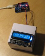
I'm still working on this project, but I've decided to use an Arduino for the user interface in the preamp. This will let me have an LCD display, some buttons for changing inputs and volume, and an IR remote control.
I'm still working on this project, but I've decided to use an Arduino for the user interface in the preamp. This will let me have an LCD display, some buttons for changing inputs and volume, and an IR remote control.
I finally got the Arduino up and running and have implemented some code that will read user button input and increment volume up/down and/or change inputs. See pics, attached below. Fun stuff!
Attachments
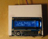
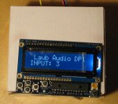
I did some more coding and have added the feature that the user can rename the inputs.
Instead of having to choose from INPUT 1, INPUT 2, INPUT 3, INPUT 4, etc. the user can enter up to 16 characters that describe the source equipment connected to the input, like "USB INPUT", "TUNER", "Berkeley Alpha", or whatever 16 characters the user chooses from the set of printable ASCII characters (ASCII 32-127).
The input names are saved to the EEPROM and loaded into memory each time the board starts up.
-Charlie
- Status
- Not open for further replies.