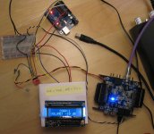
With the user interface more or less worked out on the Arduino, I decided to build up a test circuit for my input switcher on a breadboard. Even though it is a bit of a rats nest, it works - at least I can get SPDIF to run through it at 48kHz. The multiplexer IC that I am using has an enable pin, and I can change the state of that to mute the system without having to generate an "all zeros" SPDIF signal. Very convenient.
Tomorrow I check that 192kHz will pass through unscathed. Then I need to add code to the Arduino to set the pins that control the multiplexer so that I can test its input switching functionality. I don't expect any issues there.
After that I will need to test out the volume control circuitry. There is a thread around here somewhere on that already:
http://www.diyaudio.com/forums/mini...mini2x4-volume-when-using-digital-inputs.html
So far this project is looking promising!
-Charlie
I tested out the input switcher at a few different sample rates - the highest that it will pass is 96kHz. But in another forum thread, someone pointed out to me that the stray capacitance and contact resistance of a breadboard tend to cause circuits that have signals above a few MHz not work, and this is probably the case with my little hack job:

I'll have to transfer the circuit over to a prototyping PC board where everything can be soldered down, component leads trimmed, etc. and then retest it.
I'll have to transfer the circuit over to a prototyping PC board where everything can be soldered down, component leads trimmed, etc. and then retest it.
Interesting Project
What is the present state of the project?
I have for quite some wanted a system which can send separate signals to powered speakers.
In the last few days, I resumed my search, and not finding anything comparable, I had resolved to making a list of potential retail components (such as the SONOS product), for possible use in sending a signal to two powered loudspeakers. (I also only want a power cord for each speaker, nothing more.)
If you can design something which can match the performance of the SONOS (albeit at a more affordable price) in the foem of a module for DIY/OEM, I am interested. (Perhaps you have already accomplished such?)
Charl 3576854 said:I tested out the input switcher at a few different sample rates - the highest that it will pass is 96kHz. But in another forum thread, someone pointed out to me that the stray capacitance and contact resistance of a breadboard tend to cause circuits that have signals above a few MHz not work, and this is probably the case with my little hack job:
I'll have to transfer the circuit over to a prototyping PC board where everything can be soldered down, component leads trimmed, etc. and then retest it.
That's a neat idea Charlie. Keep us updated on your progress...
We don't have any wireless audio solution so providing your system works, we can certainly build a section of our website to advertise your final tweak.
Keep us updated.
OK, at last I can offer an update.
First, my apology that this project became a little stale. I have been wrestling over how to implement the volume control and remote on/off, etc. I needed to design and build some custom circuitry for this in addition to the digital input selector. This is where I got bogged down - I just could not convince myself of a "best" way to do it. I designed and simulated various circuits, but these always left me scratching my head about how they would perform or fall short, etc. I even went as far as to purchase a bunch of ICs and other parts, but then it hit me...
To send SPDIF using the AV wireless senders you are limited to a sampling rate of 48kHz. This is because the bandwidth capability of the RF wireless circuitry (that is normally used for analog video) is not high enough to accommodate a higher sampling rate. But often people have SPDIF sources at other (higher) rates, and to make sure that these sources can be sent using the wireless system the digital signal must first be downsampled to 48kHz. After some Q&A with the MiniDSP DevTeam, I discovered that their miniDIGI can be used as an ASRC, and its output stream is always at 48kHz. Great! As a bonus, the miniDIGI has built in input selection from its four spdif inputs (two coax, two Toslink) although you have to add a MBB switch to automate this. No prob. So I picked up another miniDIGI (once they were back in stock) so that I could use it in this capacity at the source. This is in addition to the two other miniDIGI boards that are used as spdif receivers for the 2x4 boards I will put in my loudspeakers.
The ah-ha moment that I had recently was about the 2x4 + miniDIGI stack. Thanks to the flexibility of these products, you can not only route the incoming spdif stream from the miniDIGI to the 2x4 (this is the normal usage) but you can also route a pair of processed channels from the 2x4 (e.g. the 2x4 outputs CH1 & CH2) back to the SPDIF output of the MiniDIGI. Because the 2x4 has the capability of using an external potentiometer for master volume control this gives us the possibility, with the addition of one more 2x4 board, to route the spdif stream to the 2x4 so that its master volume control can be used. This setup makes it possible to adjust the volume of the signal digitally before it is sent over the wireless system rather than at the loudspeakers using my previous control circuitry concept. This has several advantages...
It's been noted that when using the external volume pot, the volume = max position results in a gain loss of about 3.3 dB when using the onboard voltage source (3.3Vdc) on the potentiometer header for the 2x4. With my setup, I can make up this loss by programming a boost into the "crossover" section using the advanced biquad mode. But there is another advantage: I have often complained to the DevTeam about the lack of input PEQ/biquads in the 2x4 and 4x8 products. I use these to flatten the frequency response of my loudspeakers instead of the PEQ bands for individual drivers, which has certain subtle but important advantages. The "input" PEQ bands are globally applied to all channels in the crossovers, which are downstream. Since we have added another 2x4 board to control the volume, we can use its PEQ biquads for global PEQ as well, and this increases the number of available global PEQ "bands" by 8+6 = 14 bands! Awesome!!! My prayers have been answered.
I have been testing the volume control setup over the last couple of days. I had to iron out a couple of odd problems with the plug-in, but it seems to be working great now.
There is another advantage of this setup over my previous volume control scheme: you can connect as many wireless receivers to the system as you would like and they will all get the same volume controlled digital signal. This makes it possible to mix digital crossovers (e.g. the 2x4+miniDIGI stacks that I will use in my main loudspeakers) with analog crossovers by simply connecting the wireless receiver to a DAC feeding the analog crossover. For instance, you may only need a relatively simple crossover for a subwoofer and don't need all the processing power available with a 2x4. You could have multiple subwoofers located anywhere you would like throughout the listening space as long as they can be connected to mains power, without having to run any signal cabling. This would make it possible to investigate distributed subwoofer setups such as those espoused by Geddes:
Serious Audio: Two Great Articles on Multiple Subwoofers by Dr. Earl Geddes
I plan to do this kind of thing using four identical subs that I am building. These will be powered by plate amps that have their own built in analog LP crossovers, so there is no need for any DSP. This situation is likely quite common with plate amp powered subwoofers, so its likely to be a useful tip for others as well.
Finally, one significant advantage of the wireless SPDIF bridges is that they eliminate long and/or multiple cabling runs. These can be a source of noise pickup and can result in ground loops and other very undesirable effects. I have definitely encountered these in the past when running multiple 10-foot-long line level cables between a MiniDSP crossover and the amps located in my powered speakers. It was pretty amazing that when I would pick up and separate the cables I could form a very nice antenna that easily picked up AC hum present in the room! By eliminating cable runs between equipment this kind of problem should no longer be a concern.
When I finally manage to get my nascent system fully working (likely this will take a little while) I will post all the details of the setup for those who want to assemble something similar.
-Charlie
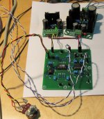
I'm making slow progress... I have everything running off of one power supply so that I can have the different boards tied together and communicating with each other. I'm temporarily making all of these connections via a solderless breadboard. At this point I have only implemented the volume control. Next up are the source selection MUXes.
Attachments
Decided to try and add an encoder to the project. This took some time to track down some interfering code, but it is working great now and was definitely worth the effort.
Contact bounce is totally eliminated by using the approach described here:
Buxtronix: Rotary encoders, done properly
There is just something so familiar and soothing about a knob...
Contact bounce is totally eliminated by using the approach described here:
Buxtronix: Rotary encoders, done properly
There is just something so familiar and soothing about a knob...
problems... problems... problems.
I've encountered a problem in which I can't get enough control range from the master volume control. This is bad enough that I will have to give up on the idea that I was so enthusiastic about just a few posts ago. It's just not going to be satisfactory as a volume control.
Here's how I've implemented the master volume control of the 2x4 and tested it out:
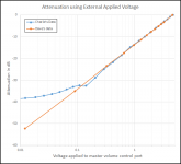
I did a regression of some data I received from another DIYer (Dave) and developed some code that converts gain to the DAC setting. This allows the user to directly set the gain (attenuation) in dB from the user GUI of the Arduino controller. It is definitely working but after using it for awhile I noticed that at the low end the attenuation range was not working properly, meaning that at some point continuing to reduce the volume did not increase the amount of attenuation (see plot below).
In order to try and spot the trouble I made some measurements of gain versus DAC setting (control voltage). A plot of my data (in blue) compared to Dave's (in orange) is provided in the attachment.
I made these measurements by doing an impulse measurement using ARTA and processing it into a frequency response. I recorded level at 1kHz for a range DAC output voltages. The voltages were calculated as: Dac setting * 5V / 4092. Using a multimeter I measured the voltages for gain settings below about -30dB and these closely agree with the calculated values. You can see that , at the "loud" end of the volume control range (near 0dB) things seem about right. When we get down to about -30dB things start to go wrong and it becomes increasingly difficult to reduce gain to the full -52dB or so that Dave reported.
If I switch the 2x4's wiper contact between the DAC set to 0 (e.g. at ground) and the wiper of a 5k ohm potentiometer with the pot also set to 0 ohms the sound level does not change. This seems to indicate that the DAC and the pot are experiencing the same lack of attenuation at the minimum setting as illustrated in the plot above.
Because of these problems, and the fact that the total available gain/attenuation range is too small to be useful for the main system volume control, I am going back to some of my original ideas for remote volume control and trying those out.
I've encountered a problem in which I can't get enough control range from the master volume control. This is bad enough that I will have to give up on the idea that I was so enthusiastic about just a few posts ago. It's just not going to be satisfactory as a volume control.
Here's how I've implemented the master volume control of the 2x4 and tested it out:
- The hardware includes an Arduino controller and a 12-bit DAC, running off of the same power supply and grounds tied together.
- The user sets the volume control setting (in dB) in the Arduino
- The Arduino sends a 12-bit level code to the DAC.
- The DAC is acts like a potentiometer between ground and a 5Vdc voltage supplied by the Arduino board. The ground is tied to the ground common point.
- The output of the DAC is connected to the input pin of the volume control on the 2x4 board.
I did a regression of some data I received from another DIYer (Dave) and developed some code that converts gain to the DAC setting. This allows the user to directly set the gain (attenuation) in dB from the user GUI of the Arduino controller. It is definitely working but after using it for awhile I noticed that at the low end the attenuation range was not working properly, meaning that at some point continuing to reduce the volume did not increase the amount of attenuation (see plot below).
In order to try and spot the trouble I made some measurements of gain versus DAC setting (control voltage). A plot of my data (in blue) compared to Dave's (in orange) is provided in the attachment.
I made these measurements by doing an impulse measurement using ARTA and processing it into a frequency response. I recorded level at 1kHz for a range DAC output voltages. The voltages were calculated as: Dac setting * 5V / 4092. Using a multimeter I measured the voltages for gain settings below about -30dB and these closely agree with the calculated values. You can see that , at the "loud" end of the volume control range (near 0dB) things seem about right. When we get down to about -30dB things start to go wrong and it becomes increasingly difficult to reduce gain to the full -52dB or so that Dave reported.
If I switch the 2x4's wiper contact between the DAC set to 0 (e.g. at ground) and the wiper of a 5k ohm potentiometer with the pot also set to 0 ohms the sound level does not change. This seems to indicate that the DAC and the pot are experiencing the same lack of attenuation at the minimum setting as illustrated in the plot above.
Because of these problems, and the fact that the total available gain/attenuation range is too small to be useful for the main system volume control, I am going back to some of my original ideas for remote volume control and trying those out.
Attachments
While I am waiting for some parts to arrive for the new(est) attempt at a volume control circuit I thought I would go back and try to get the input switching circuit working again. The MUX will be connected to the spdif selection header on the miniDSP and will select from the four spdif input channels that are available through the board. But I also want to be able to connect additional spdif inputs to the MUX and route them to the miniDIGI board as well. My original input switcher circuit had an spdif -> TTL converter and I was able to get this working again and clean up the breadboard to all the components are not just sticking off into space and picking up noise. But alas my MUX is an HCU type and only operates at 5V, so I need to get a 3.3V compatible HC type MUX before testing this out further. Since the part is only $1.50 I will probably wait until I need some other parts before ordering. Since I got the identical pinout HCU part to work before, it's just a matter of getting the new part in and plugging it into the board. Well, it's that simple on paper at least!
The next attempt at a volume control circuit will use some venerable 4-channel VCAs that use an analog DC input to set levels. These aren't as good as modern volume control ICs in terms of noise or distortion, but they will be fine in the short term at least. If I can get this concept working I will test it out and post some measurements of the performance. The VCAs can provide both gain and attenuation. Having access to global gain in the signal chain will be very handy, and will allow me to more easily interface with amplifiers that have higher input sensitivities.
The next attempt at a volume control circuit will use some venerable 4-channel VCAs that use an analog DC input to set levels. These aren't as good as modern volume control ICs in terms of noise or distortion, but they will be fine in the short term at least. If I can get this concept working I will test it out and post some measurements of the performance. The VCAs can provide both gain and attenuation. Having access to global gain in the signal chain will be very handy, and will allow me to more easily interface with amplifiers that have higher input sensitivities.
Still waiting for parts to arrive, so continuing to fiddle...
I thought it would be useful to add a volume controlled analog stereo output so that the preamp could be connected to local amplifiers if desired. Today I connected a great little ES9023 Sabre DAC board from DIYINHK to the MiniDIGI I2S lines and did some measurements. I'm very impressed.
The DAC outputs will be connected to a volume control section and an output buffer. In the short term I plan to implement the local volume control using another VCA, the SSM2018T. I've had a few of these kicking around for several years and I can finally implement them in a design. I plan to use a modern digital volume control IC when I make refinements to the system in the future.
One other project that I am currently working on is a unity-gain headphone amplifier (see: http://www.diyaudio.com/forums/headphone-systems/260003-my-lm5532-headphone-amplifier-project.html). I plan to drive the head amp using the analog outputs from this preamp.
Die parts are hier! I finally received an order of parts that I need to complete the spdif input switcher for the preamp and make some more progress on my headphone amplifier project. In the meantime I've been doing some coding...
I've always been interested in Manchester encoding and about a year ago I finally managed to figure out what this is all about. Since I have been considering different ways to implement communication between the preamp and the loudspeakers in recent weeks, I went back and re-examined the topic, specifically regarding differential Manchester encoding. I came up with some nascent ideas of how to construct algorithms for encoding/transmission, and reception/decoding, of this kind of signal, and how to implement the necessary communication hardware. Since it encodes the clock, only needs one "wire", and is one-way, differential Manchester encoding is a very practical way to send commands from the preamp to a PIC/AVR (like an Arduino) in a loudspeaker. This can include multiple, addressable loudspeakers or loudspeaker pairs, e.g. you could turn on or off loudspeakers in different rooms, or change the balance or level of any speaker, by sending it an appropriate command, or whatever else you desire. The PIC in the loudspeaker receives the command over the communication line and then carries out the action. These things are inexpensive and are relatively easy to program, so why not make use of them here?
I've managed to write and successfully compile (e.g. without generating errors) the code for the transmitter and receiver side of the communication line. Every programmer knows that means little, and the real work is ahead to test and debug the running code, but hopefully this will not be too painful.
If that gets old I can always fire up the soldering station and put some of those new parts to use! 😀
After the usual hair pulling and gnashing of teeth throughout two days of debugging I've managed to get the differential Manchester encoding communications code up and running! This is really, really great. With a little added hardware I can now implement the volume control (and anything else that a PIC can control) at the loudspeaker from the preamp "base station". I still need to test this out over the wireless links, so hopefully I can try that out in the next few days.
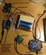
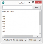
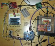
I realized that I could not be sure that the code that runs the preamp would not have a conflict with the code that performs the communication between the preamp and the loudspeakers unless I tested it. So I did a big code merge, tweaked a few settings, and gave it a try. And... success! I can send an integer value for the volume level in decibels as text through the communications link as fast as I can change the volume at the preamp. I monitored the receiver using the Arduino Serial Monitor (see attached pic). I've also thrown in a pic of the project, sprawled out on the desk here, with some labels to identify the different parts of the system.
The SPDIF output will be sent to a miniDSP crossover in the loudspeakers. The DAC output will route to panel jacks on the back of the preamp. I'll connect these to my headphone amplifier. Not shown in the picture are the boards for USB (input) --> SPDIF and Analog (input) --> SPDIF.
The SPDIF output will be sent to a miniDSP crossover in the loudspeakers. The DAC output will route to panel jacks on the back of the preamp. I'll connect these to my headphone amplifier. Not shown in the picture are the boards for USB (input) --> SPDIF and Analog (input) --> SPDIF.
Attachments
Yet Another Update:
In order to send the volume level info over a system that is designed for "AC" signals I had to make a couple of small additions to the preamp code. I also had to build additional TX and RX interfacing circuits, but these were pretty simple affairs that I had thoroughly vetted in SPICE. I finally finished all of this last night, so this morning I connected everything and gave it a try. After some minor debugging using a direct connection between TX and RX I moved on to the wireless links. I could not be 100% sure that the wireless links would work in this capacity until testing it and to my relief this worked great!
I'm now sure that I can send commands from the preamp to the loudspeakers over the wireless links to carry out control of anything within the loudspeaker. This could be volume control or power on/off as I have previously envisioned but it might possibly be anything, as long as I can carry out that control action from the PIC in the loudspeaker. This adds a lot of flexibility to the project and I will have to think about what kind of new possibilities this presents.
Now that the data link is working, I'm developing the hardware on the receiver (loudspeaker) side. A PIC microcontroller will receive commands, e.g. volume control from the preamp. The PIC will set the output level of a DAC, the output of which is a DC control voltage for a 4-channel VCA. The VCA receives the outputs of the miniDSP crossover and scales the voltage level (up or down), thus controlling the volume, before sending the signal on to the amplifiers. This will allow gain to be applied to the miniDSP crossover output, which will be helpful on a variety of fronts. I am hopeful that with some careful implementation the distortion added by the VCA will be minimal.
The DAC is controlled via I2C from the PIC, and I plan to insert an isolator IC between them. The isolator will allow separation of power and ground between digital and analog supplies. I have a few on order now, and I will need to solder them into a proto shield for the PIC before I can use them with the other hardware. I'll post an update once I get a chance to test all of that out.
The DAC is controlled via I2C from the PIC, and I plan to insert an isolator IC between them. The isolator will allow separation of power and ground between digital and analog supplies. I have a few on order now, and I will need to solder them into a proto shield for the PIC before I can use them with the other hardware. I'll post an update once I get a chance to test all of that out.
Update:
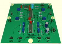
Have made a little progress. Built a backpack for the Arudino in each loudspeaker with the circuit for the differential Manchester code receiver and an I2C isolator. Then I designed a PCB for the 4-channel VCA. This will do the actual volume control and be inserted in the signal chain between the output of the miniDSP crossover and the amplifiers. Pictures are always fun, so here is a mockup of the board:
Have made a little progress. Built a backpack for the Arudino in each loudspeaker with the circuit for the differential Manchester code receiver and an I2C isolator. Then I designed a PCB for the 4-channel VCA. This will do the actual volume control and be inserted in the signal chain between the output of the miniDSP crossover and the amplifiers. Pictures are always fun, so here is a mockup of the board:
Attachments
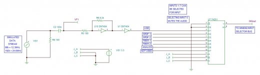
Things are rolling right along now... Today I got the SPDIF input switching network functioning (on a breadboard at least). I had tried this before, but because the TTL level is 3.3v and I was using an HCU type logic IC it wouldn't work. I ordered an HC type but while I was waiting for it to arrive I got sidetracked. I finally found some time today to revisit this, and plug in the new IC.
This section of the project is part of the "preamp" and selects from spdif streams (in TTL format). These include the four streams available on the miniDIGI header, plus a USB input and an analog input.
The basic schematic is shown below in the attached pic.
This section of the project is part of the "preamp" and selects from spdif streams (in TTL format). These include the four streams available on the miniDIGI header, plus a USB input and an analog input.
The basic schematic is shown below in the attached pic.
Attachments
Do you know that deflated feeling you get when you spend a couple of days building up a circuit board only to find that it doesn't work? And then after a few hours of diagnostic testing you find that you made a fatal mistake in the wiring and have to start all over?  This is where I find myself right now.
So, Its back to the bread boards to double check everything before another mad, mad, mad protoboard effort.
This is where I find myself right now.So, Its back to the bread boards to double check everything before another mad, mad, mad protoboard effort.
Whew! I ripped through the soldering process for a couple more protoboards and now I have everything working again, even better than before. I split my previous attempt (which I will write off as a learning experience) into two separate boards. Where before I was forced to cram things into the available board space, now I could place components in a more logical manner. The various boards are connected by a rats nest of wiring, but I can put up with that for now - its only a prototype! It just has to work correctly, not look pretty.
I still have a few things to debug and test out, but I am steadily working my way to a fully operational battle station. While I am pondering what to do next, I'm also dreaming up inexpensive ways to throw some kind of chassis together. I think I can aim higher than a bunch of boards and wires sitting on the table... I would order a chassis from Ebay, but I need a window in the panel for the Arduino's 2x16 display. I may cobble together something from aluminum sheet metal and wood, since I can work all of that on my drill press. The front panel might need to be made from hardboard until I get the layout finalized, and figure out just how many buttons and other controls I want there. There will be least a few buttons and a rotary encoder...
I still have a few things to debug and test out, but I am steadily working my way to a fully operational battle station. While I am pondering what to do next, I'm also dreaming up inexpensive ways to throw some kind of chassis together. I think I can aim higher than a bunch of boards and wires sitting on the table... I would order a chassis from Ebay, but I need a window in the panel for the Arduino's 2x16 display. I may cobble together something from aluminum sheet metal and wood, since I can work all of that on my drill press. The front panel might need to be made from hardboard until I get the layout finalized, and figure out just how many buttons and other controls I want there. There will be least a few buttons and a rotary encoder...
Volume control board update:
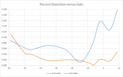
A couple of days ago I received the prototype boards that I had made for the VCA circuit that does the volume control. I've had the time to build a board and do some frequency response and distortion testing. The board works perfectly and the frequency response is blameless. I wanted to measure the distortion performance, since the datasheet indicated that it would be between 0.01% - 0.1% or so. I found that this was the case (see attached plot). Distortion levels remain below 0.1% when the gain is less than about -6dB and climb to 0.2% at +10dB gain. Distortion is made of mostly second order and third order distortion remains low. This is about what I expected and I can live with this level of performance for now. Later on this year I may implement a digital volume control that will have much lower distortion at all gain levels.
At this point I have built and tested pretty much all of the different parts of the system. It's still a sprawl of wires and boards, and will probably remain like that until after the NorCal DIY Audio show late next month. I've got speakers to built in the mean time, and this is supposed to be part of that whole system, so I am scrambling to get everything done at this point since there are only a few weeks to go.
Attachments
- Status
- Not open for further replies.