They look soooooo nice... verry innovative. Congratulations, looking forward for more info about them.
Last edited:
It also has led me to realize that the diameter of the spider is generally proportional to the linearity of the restoring force, all else equal. As the spider diameter increases, the angle which is formed between the radiating plane and the spider itself becomes more linear with respect to excursion.
Small-angle approximation - Wikipedia, the free encyclopedia
Which I suppose is why subwoofers get ever-larger spiders as their Xmax increases. Whether this is just common knowledge or just a hidden rule of thumb, well, who knows. In any case this means that as long as the spider can be acoustically transparent, it should be as wide as possible. In most cases this would be such that the mounting ring for the spider should just be able to fit through the same hole as intended for the entire basket.
EDIT: To be specific, where Hooke's law dictates F = kx, a larger spider linearizes x, not k. The design of the spider to linearize the stiffness k is a different matter.
Last edited:
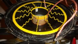
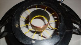
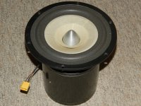
Finally some progress. Magnetic structure is finally like it should be.
now time to start with the voicecoil. Already made of alu but too much eddycurrents resulting in overdamping (tried to use a stable current source to overcome this but didn't help alot). Looking for kapton hopefully with better results.
some pics
.JPG")
.JPG")
.JPG")
now time to start with the voicecoil. Already made of alu but too much eddycurrents resulting in overdamping (tried to use a stable current source to overcome this but didn't help alot). Looking for kapton hopefully with better results.
some pics
Attachments
By the way, please test those and give us a graph of mm vs newtons. 🙂
Will do.
@Jef
Very nice work there.
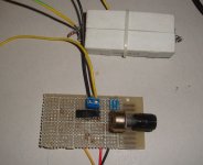
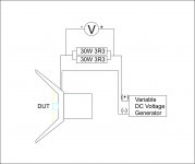
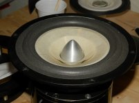
I did a first test today. I used an empty frame and a voice coil just to see how x will vary in respect to input current. Please refer to pictures for details of this assembly.
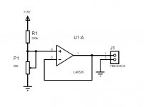
I made a small variable DC voltage generator, very simple using a power opamp the LA 6520, attached you can find the schematic but bare in mind the pins on the schematic dont correspond. For LA6520 Input + is pin 1, Input - is pin 2 and Ouput is pin 3. Chose this opamp because i had it and it can output up to 500mA. Resistor values chosen to reach max 2V. I didnt had a 330k resistor so used 3 x 1M in parallel.
X measurement is not very accurate at the moment due to the tight space within frame and lack of a laser sensor but i was more interested in the slope rather than the values per say.
The result graph attached shows the excursion in up direction only, no other mass added than the one of the voice coil.
At about 3.5mm the voice coil leaves the gap so the force will suffer... theoretically. As you can see due to high field strength the fringe field around the gap still keeps it linear a little more above that value after that it gets into a saturated region altho i did push it to about 10mm excursion.
I'm very pleased with how it performed on this test. Next i will test with mass and in both directions.
Attachments

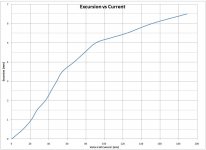
Interesting. Up until ~90 mA the stiffness seems to be quite linear.
For your graph of excursion vs current, was current calculated based on voltage, or is your power supply actually controlling the current directly? The resistance will go up as the coil heats, so the current will continue to diverge from voltage until thermal equilibrium is reached.
For your graph of excursion vs current, was current calculated based on voltage, or is your power supply actually controlling the current directly? The resistance will go up as the coil heats, so the current will continue to diverge from voltage until thermal equilibrium is reached.
The current was calculated with the series resistor. This was made from 2 parallel connected 30W 3R3 resistors. Temperature effects on the values of these resistors at those current levels are negligible.
Awesome work Hentai....
It would be interesting to compare your spider with a “ standard one” using the same setup. What is the material you are using for your spider, any idea if hold over time.
Jef, nice to see you are making progress, keep us updated.
Take care
It would be interesting to compare your spider with a “ standard one” using the same setup. What is the material you are using for your spider, any idea if hold over time.
Jef, nice to see you are making progress, keep us updated.
Take care
Thanks Frank,
Material is PLA. Will do such test yes. Does it last in time dont know yet but i will be hitting it with 2Hz for a couple of days and see what happens.
Meanwhile a short video:
http://youtu.be/uxqd4jdyrHw
Material is PLA. Will do such test yes. Does it last in time dont know yet but i will be hitting it with 2Hz for a couple of days and see what happens.
Meanwhile a short video:
http://youtu.be/uxqd4jdyrHw
That is so cool. You should push this concept as far as it can go (no pun intended).Thanks Frank,
Material is PLA. Will do such test yes. Does it last in time dont know yet but i will be hitting it with 2Hz for a couple of days and see what happens.
Meanwhile a short video:
Project Ryu New Spider for Field-coil Loudspeaker - YouTube
Thank you very much.
Yes it has some key features which makes it particularly attractive (at least for me):
- you can adjust stiffness by changing the number of spokes without affecting linearity
- you can adjust linearity by changing the rolls of each spoke
- good grip on voice coil
- good connection to frame
- small sound radiating area
- small mass
- cheap and easy to manufacture
Marry Christmas to all,
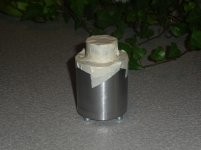
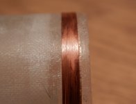
I have been practising making voice coils, and now I believe I got to a point where I can bee satisfied. I wanted to wind inside and out on the former, to double the areal where the copper conduct the energy to the voice coil former.
Also I have been trying different materials for the cones, I am very happy with Depron but I also tried some special paper impregnated with epoxy with good result. So I am still confused on what material to use on the “final ones”
Here is some pictures.....
Attachments


Marry Christmas to all,
..So I am still confused on what material to use on the “final ones”
Here is some pictures.....
only your ears can decide. if i had these skills, i'd be very tempted to try various cone and former materials on the same driver type.
very nice work indeed.
Marry Christmas to all,
I have been practising making voice coils, and now I believe I got to a point where I can bee satisfied. I wanted to wind inside and out on the former, to double the areal where the copper conduct the energy to the voice coil former.
Also I have been trying different materials for the cones, I am very happy with Depron but I also tried some special paper impregnated with epoxy with good result. So I am still confused on what material to use on the “final ones”
Here is some pictures.....
Should consider how well two cones of any type can be duplicated with accuracy. My vote would be towards the depron for this reason, but if the doped cones can be matched with the same accuracy and work better, what the hey. Perhaps pushing both to their upper limits would shed some light on the subject.
Will you be using Hentai's spider design?
Thanks
Hopefully I will know soon whist material to use, right now I am leaning to Depron due to the low weight (1,2 grams). I did try some different combination of materials, to find the combos I like the best. But the Paper/Depron is not bad at all, all tow the weight is a bit higher (2,5 grams)
I am using the spiders made by Hentai, he was kind enough to let me use them. A big thanks to him.
Take care
- Home
- Loudspeakers
- Multi-Way
- Project Ryu - DIY Field Coil Loudspeaker