Have to pass on the props. I have seen many a post on magnet sims, but never someone actually build what they were talking about.
Hello and thank you for your comments.
I have returned with more details. I was in hurry and i missed a few questions from LineSource.
I see no major problems with using this type of unit as a mid-bass like in the Daniel Hertz loudspeaker. A heavier cone would be more advantageous i guess in such application and one can do that by adding a mass ring right at the base of the cone. Or one can just lower the current through the field coil. (one of the greatest feature of these kind of units).
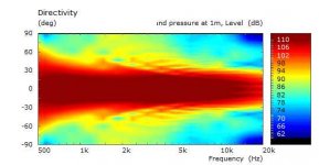
As LineSource pointed out for 12 inchers 1khz is about the 90 deg point. Once the whizzer cone is added, things change. From low high frequencies (1-3Khz) , depending on size ( mostly voice coil diameter as i have noticed) up to about 5-7kHz both cones work together and after that the whizzer cone has the significant role in output. Therefore the directivity pattern is pretty different from a normal mid-bass unit. A 2" voice coil makes life hard in this matter tho.
Below is an AxiDriver simulation of a whizzer cone i want to try out. This is just the whizzer without cone. Reality will be different because there is no way to tell how it will interact with the main cone and the simulation has the whizzer connected to chassis through wide surround.

There is much work i need to do to determine whizzer cone parameters. I have simulated various shapes, diameters and heights. Haven't done much regarding a possible phaseplug.
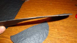
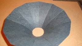
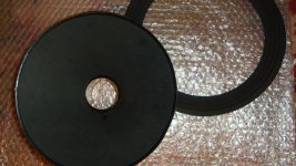
This weekend i started to test some cone shaping. So far i tried straight cones from a single plain sheet and petal cones. These are just try-outs but here are some pics:


To stiffen the cone i layered the paper like a sandwich putting a higher density one in the middle. Should try the opposite too.

I have returned with more details. I was in hurry and i missed a few questions from LineSource.
I see no major problems with using this type of unit as a mid-bass like in the Daniel Hertz loudspeaker. A heavier cone would be more advantageous i guess in such application and one can do that by adding a mass ring right at the base of the cone. Or one can just lower the current through the field coil. (one of the greatest feature of these kind of units).
As LineSource pointed out for 12 inchers 1khz is about the 90 deg point. Once the whizzer cone is added, things change. From low high frequencies (1-3Khz) , depending on size ( mostly voice coil diameter as i have noticed) up to about 5-7kHz both cones work together and after that the whizzer cone has the significant role in output. Therefore the directivity pattern is pretty different from a normal mid-bass unit. A 2" voice coil makes life hard in this matter tho.
Below is an AxiDriver simulation of a whizzer cone i want to try out. This is just the whizzer without cone. Reality will be different because there is no way to tell how it will interact with the main cone and the simulation has the whizzer connected to chassis through wide surround.
There is much work i need to do to determine whizzer cone parameters. I have simulated various shapes, diameters and heights. Haven't done much regarding a possible phaseplug.
This weekend i started to test some cone shaping. So far i tried straight cones from a single plain sheet and petal cones. These are just try-outs but here are some pics:
To stiffen the cone i layered the paper like a sandwich putting a higher density one in the middle. Should try the opposite too.
Attachments
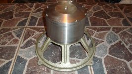
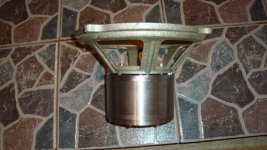
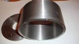
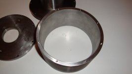
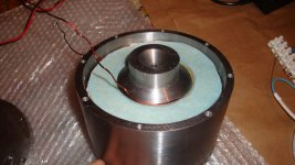
Things are progressing.


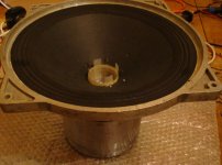
Here's the assembled structure w/out fieldcoil on a vintage 12" Al frame:


I will use nicer screws in the end, these are what i had on hand. 😛
Here's the assembled structure w/out fieldcoil on a vintage 12" Al frame:
I will use nicer screws in the end, these are what i had on hand. 😛
Attachments
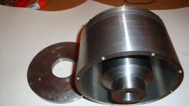
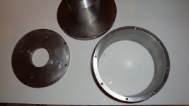
Wow, that motor structure looks great. 😀 Do you have drawings of the various machined parts you could post in the event that others might want to copy your efforts?
Hello Kevin, yes, after some testing of the motor and if no major adjustments are needed to current design i will post the full schematics.
Pretty soon i hope 😀
Pretty soon i hope 😀
more info will come, pretty busy month but will resume the project soon.
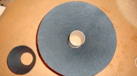
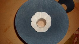
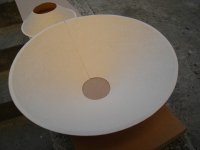
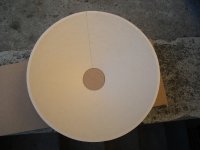
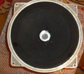
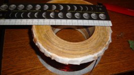
But here is a little teaser. A friend and countryman helped me and manufactured a couple of mullbery paper cones. Here are some shots:


But here is a little teaser. A friend and countryman helped me and manufactured a couple of mullbery paper cones. Here are some shots:
Attachments
Last edited:
I'm also making exponential curved cones, from 12 petals, washi paper. I'm still experimenting with stiffening the washi.

I will test everything i can. Straight and exponential and maybe hyperbolic but i fear the curvature will be too great.
So far mass is well within my goal. I will perform as much tests and measurements as i can and my equipment allows on all cones and whizzer types. Hopefully phase plug variations too.
Attachments
Last edited:
All this is really really great.
I would risk two noobish questions :
1. Nowhere I read a reference about the voice coil inductance. Isn't it BTW the limiting factor in bandwidth extension ? Then, isn't a smaller VC more adaptated for this issue ?
2. For the cone and the whizzer, with the skills you have, aren't you considering to make a one piece molded one, from your own paper mix over a machined shape ? I guess you could even make a press for exponential parts.
Thats some beautiful machining on the magnet structure. Cones look very functional too. I think I would stick with the conical single seam cone. The multisection cone looks like it will be hard to make with strength. You can experiment with different cone stock, from heavily calendared manila card stock to blotter paper. If I remember the old Lowther units used a thin manila card stock. I've seen them with square ruling on the back as if they used a type of graph paper.
Good work. We look forward to the results.
David
Good work. We look forward to the results.
David
Hello,
Radugazon, those are good questions. Inductance of voice coil is one of the problems I'm fighting. You noticed that the higher diameter of voicecoil, the thinner wire and the underhung motor structure, all will lead to a higher inductance. I have given it a lot of thought and I have a model that i will present here as soon as i will take some pictures and do some measurements to verify my calculations.
In my model tho what i wanted to see is how much of an influence will a shorting ring on a FC motor will have on impedance curve, how much of an influence will the low impedance field coil itself have on the impedance (if any), influence of eddy currents.
I chose 2" voicecoil because i wasnt sure how rigid i could make the cone and i was afraid a smaller diameter will stress it too much. The thin wire at first although allows for greater lenght in the gap increases the number of turns and so increases inductance but there is a way to wind it to get around that... i think 🙂
Once i will determine which type of cone works best i might try a pressed cone. I already discussed different mixtures for cone material. It will be pretty costly tho so this will be an option if i will continue to build the cones.
David, i also have a couple of stock cones from recone kits i will try and compare.
Hello,
The thin wire at first although allows for greater lenght in the gap increases the number of turns and so increases inductance but there is a way to wind it to get around that... i think 🙂
QUOTE]
....cross winding? Time consuming or even possible?
Beautiful work!
Peter
Im not really sure what you mean by cross winding applied to voice coil.
What i am considering is 2 coils in parallel. One on the inside and one on the outside of the former.
What i am considering is 2 coils in parallel. One on the inside and one on the outside of the former.
Have you thought about the spider design and materials also? It would be intressting to see what kind of DIY solutsion would match the coals for a project like that.
Moving forward,
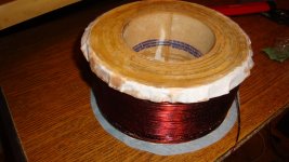
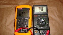
This weekend i was able to perform a few tests. Placed the field coil inside and did a few measurements of field strength. FC measures 7.1 ohms and 124mH. The higher DC resistance will require a higher supply voltage than my initial goal.
Because of the enamel coating the wire thickness is smaller, for a 5.3 ohms FC the motor structure will need to be a tad bigger.


In order to determine the field strength i had to measure BL, after that knowing L i could determine B value. BL can be computed by measuring the impedance of a complete assembly so i used a factory cone to quickly put together the loudspeaker.


I used an 16V/7.5A IBM power supply at first and that gave a current of about 2.2A through the FC. I made another power supply with a multitap transformer a 35A bridge and 2 x12000uF/56V to test other supply voltages.
Results are the following:
A---------- V---------- Rdc-------- Fs--------- Qes-------- SPL-------- Mms--------- BL--------- B
2.38------- 17.98------ 13.47------ 33.65------- 0.258------ 96.47------ 38.94------- 20.72------ 1.48
2.52------- 19.34------ 13.57------ 33.65------- 0.255------ 96.52------ 38.94------- 20.93------ 1.50
2.65------- 20.3------- 13.59------ 33.65------- 0.2496----- 96.62------ 38.94------- 21.17------ 1.51
4.33------- 33.6------- 13.74------ 33.65------- 0.21------- 97.34------ 38.94------- 23.13------ 1.65
It seems that FEMM simulations predicted a good value and I am right on target with a B value of 1.5T at 2.5A. The factory cone is heavy so the SPL isn't spectacular.
at 2.5A heat is not an issue, at 4.33A the motor structure was warming up but still not a big problem, you can also observe the rise in Rdc because of that.


Next i will get a temperature probe and a variable power supply with high current capability (build one maybe?) so i can plot Temp, BL, B and Rdc at various voltages/currents.
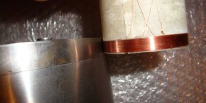
Here is a short video showing remanence in pole piece.
Youtube Link
Allar, so far i have prepared a number of factory spiders, right now im not so hyped about wood spiders and that kind of thing but i might try something like that. The mechanical - acoustical transducer is the most challenging part i guess.
Well more will follow.
This weekend i was able to perform a few tests. Placed the field coil inside and did a few measurements of field strength. FC measures 7.1 ohms and 124mH. The higher DC resistance will require a higher supply voltage than my initial goal.
Because of the enamel coating the wire thickness is smaller, for a 5.3 ohms FC the motor structure will need to be a tad bigger.
In order to determine the field strength i had to measure BL, after that knowing L i could determine B value. BL can be computed by measuring the impedance of a complete assembly so i used a factory cone to quickly put together the loudspeaker.
I used an 16V/7.5A IBM power supply at first and that gave a current of about 2.2A through the FC. I made another power supply with a multitap transformer a 35A bridge and 2 x12000uF/56V to test other supply voltages.
Results are the following:
A---------- V---------- Rdc-------- Fs--------- Qes-------- SPL-------- Mms--------- BL--------- B
2.38------- 17.98------ 13.47------ 33.65------- 0.258------ 96.47------ 38.94------- 20.72------ 1.48
2.52------- 19.34------ 13.57------ 33.65------- 0.255------ 96.52------ 38.94------- 20.93------ 1.50
2.65------- 20.3------- 13.59------ 33.65------- 0.2496----- 96.62------ 38.94------- 21.17------ 1.51
4.33------- 33.6------- 13.74------ 33.65------- 0.21------- 97.34------ 38.94------- 23.13------ 1.65
It seems that FEMM simulations predicted a good value and I am right on target with a B value of 1.5T at 2.5A. The factory cone is heavy so the SPL isn't spectacular.
at 2.5A heat is not an issue, at 4.33A the motor structure was warming up but still not a big problem, you can also observe the rise in Rdc because of that.
Next i will get a temperature probe and a variable power supply with high current capability (build one maybe?) so i can plot Temp, BL, B and Rdc at various voltages/currents.
Here is a short video showing remanence in pole piece.
Youtube Link
Allar, so far i have prepared a number of factory spiders, right now im not so hyped about wood spiders and that kind of thing but i might try something like that. The mechanical - acoustical transducer is the most challenging part i guess.
Well more will follow.
Attachments
-
 DSC02937.JPG508.5 KB · Views: 233
 -
 DSC02962.JPG393.2 KB · Views: 243
 -
 DSC02966.JPG396.6 KB · Views: 223
 -
 DSC02965.jpg300.3 KB · Views: 179
 -
 DSC02947.JPG509.8 KB · Views: 167
 -
 DSC02946.JPG465.2 KB · Views: 187
 -
 DSC02942.jpg296.9 KB · Views: 221
 -
 DSC02940.jpg298 KB · Views: 199
 -
 DSC02939.JPG484.6 KB · Views: 199
 -
 DSC02938.JPG506.8 KB · Views: 214
Last edited:

"Heavy is good, heavy is reliable" Boris the Blade
An externally hosted image should be here but it was not working when we last tested it.
Attachments

I wish I had the knowledge, tooling, and knowledge to do such work. Great job!
And yes, I realize I said knowledge twice. 😀
And yes, I realize I said knowledge twice. 😀
Nice, it is intressting to see some results with diffrent FC steering Cant wait when the right cone is beeing fitted and the measuring is beeing repeated.
About the power supply: maybe something from CCCP times, that shouldent be so hard to find, will do for testing? '
Impressive work indeed!
About the power supply: maybe something from CCCP times, that shouldent be so hard to find, will do for testing? '
Impressive work indeed!
- Home
- Loudspeakers
- Multi-Way
- Project Ryu - DIY Field Coil Loudspeaker