Hi Nick
here is a spreadsheet i made to make it easy with straight paper cones from plane sheets of paper. For curved cones made from petals hornresp is a great tool.
I look in my JBL collection of datasheets, i think they published some physical dimensions of the magnetic pot. If not maybe you can provide the dimensions to run some sims.
Attachments
I have the specs for the coil Im going to try, but there at home and Im at work. If I remember ill post them tonight.
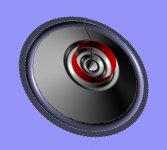
The quick and dirty dimension for the pot structure are 6 1/2 inch outer diameter. The wall is 7/16" thick and the height is 2 1/8" on the outside. The area im going to fill with the coil is about 5 1/2 outer diameter 3" inner diameter. And the coil can be around 1 1/2" tall. Im going to use 18 gauge copper wire. It will be around 1000 turns. I only need 12 kilogauss in the gap. So it doesn't need to be a big at the beast you made, LOL.
Nick
Thanks to you Hentai, Ive got the dimension for my cone. Im going to go to the art supply store tonight after work and look for some things to try.
Were you ever successful in making your own surrounds? Since Ill need my qts in the 20's, Im guessing I was a suspension that's pretty tight?
Nick
Were you ever successful in making your own surrounds? Since Ill need my qts in the 20's, Im guessing I was a suspension that's pretty tight?
Nick
Hi Nick,
I've made my own surrounds for compression drivers only. For cone speakers you will find a large variety in speaker component stores to suit your needs.
Yes you will need a tight suspension for a horn, specially a long horn but also keep in mind two things, suspension will matter mostly at Fs and below and Qts is mostly influenced by Qes.
@von.ah thanks for your words and encouragement.
I've found a few surrounds but for accordians there isn't many options.
The horn is a back horn with about an 8 foot path. Its a copy of a jbl c550 or 4520. But I modified it a little bit. Its a little taller then the jbl design.
For the spider, I'm just using an aftermarket copy of a jbl flat spider. As for surrounds, I was going to try an altec style one with multilpe rolls. Need to buy a wooded tester though first,lol.
Sent from my Garminfone using Tapatalk
I bought 2 20 by 30 inch sheets of cold press heavy paper. Its 300 grams for a square meter. It was cheap and I know I'm probably going to trash it trying to make a cone with it. I don't think I can cut one cone from a single sheet. So I might do a half per sheet. That way there's a seam on each side of the cone. The seam will give it more rigidity. I've even though about doing it in 4 pieces. It would make the cone stronger as far as flexing goes.
Nick
Nick
I bought 2 20 by 30 inch sheets of cold press heavy paper. Its 300 grams for a square meter. It was cheap and I know I'm probably going to trash it trying to make a cone with it. I don't think I can cut one cone from a single sheet. So I might do a half per sheet. That way there's a seam on each side of the cone. The seam will give it more rigidity. I've even though about doing it in 4 pieces. It would make the cone stronger as far as flexing goes.
Nick
Maybe try an uneven multiple, like five or seven sections - the 5 "petal" surround used on some of the Vifa speakers really does work very well and is very good at reducing resonances.
Hey Jack, nice to see you on-board.
Here is my thoughts....
If you are going for a ultra light cone for your woofer, you could use 3mm depron. I made a cone for a 6” full range and it had a weight of 0,9grams (hard to beat), but the material was not stiff enough to support high frequency. But this might bee a interesting material for a woofer, and you can make it very strong by making it as a composite material with paper on each side. See picture.
Also depron has a high degree of self damping, so if you are up to experiment this might work for you.
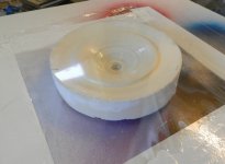
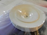
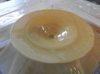
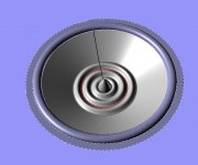
I have also added some pic's of how I do the vacuum cone this one I used the primer 92 epoxy it's curing up a bit harder that the aero-epoxy. also I got some epoxy that can stand up to 180 degrees C for voice coils.
Take care
Here is my thoughts....
If you are going for a ultra light cone for your woofer, you could use 3mm depron. I made a cone for a 6” full range and it had a weight of 0,9grams (hard to beat), but the material was not stiff enough to support high frequency. But this might bee a interesting material for a woofer, and you can make it very strong by making it as a composite material with paper on each side. See picture.
Also depron has a high degree of self damping, so if you are up to experiment this might work for you.
I have also added some pic's of how I do the vacuum cone this one I used the primer 92 epoxy it's curing up a bit harder that the aero-epoxy. also I got some epoxy that can stand up to 180 degrees C for voice coils.
Take care
Attachments
Last edited:
Hey Jack,
Ya that's in line with what I was thinking. But I'm thinking no more then 3 seams. I can see the helping with rigidity of the cone. But I can also see them creating a seal problem where the surround attaches to the cone. But I'm not at that point. I'm just trying to make one that looks like a cone first.
Hi Frank, That sounds like a good idea. I've even thought of trying carbon fiber. I've read about your use of depron. To be honest, I know nothing about it. But I'm open to the possibility. Since I've never done this before I want to crawl before I walk. So for now I'll stick to paper. After I've made a few successful paper cones then I'll move to a more advanced technique. I need a wood lathe first to make the mold with?
Nick
Hello gents,
Nick if the 15 incher will be used in BLH than rigid suspension is not really mandatory as i reckon you wont drive them like in the pro world. Softer suspension might be more revealing and better bass at lower level listening but you need a strong motor.
Alright some data now on the development of my 12 incher ( I know Frank's been waiting 😀 ). I started procesing the data on the reverse way i introduced it so first version tested was with the voice coil no 3.
Characteristics:
Paper former
Nominal Diameter: 50mm
Height: 5mm
Wire diameter: 0.15mm
Wire: ECW
Dual voice coil, 2 layers each.
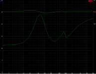
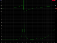
This is the heavy voice coil, lots of copper in it. Below you can see impedance curve of one such coil.
You will notice high inductance, its the big coil (the other vcs will get lower haha) Also the disturbance around 1k. Havent figured that one yet.
Fs just below 60Hz still in my good zone.
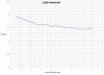
I wanted to plot Le(x) and BL(x). Le(i) and Kms(x) would be great too but i still need to find some practical solutions. Even Le(x) and BL(x) not sure how reliable they are but they are pretty close to FEMs and also similar in variations denoting the influence on each other.
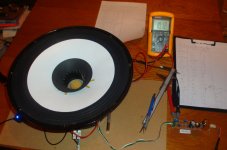
I couldnt move the cone with pressure but since i had 2 voice coils i put a DC voltage on one coil and measured impedance on the other. The DC voltage will created an offset in voicecoil position so i can see it's influence on those parameters.
To adjust the voltage i made a circuit based on LM2576T-adj. Using a multiturn pot can grant you a high enough sensitivity to adjust in mV range. Schematic is the easy datasheet one.
Right now i got the data for +/-3.5mm excursion. Looks pretty good with the normal tilt towards the inside of the motor where fringe field is stronger. Negative values indicate position inside motor, positive values indicate position outside the motor.
Even tho inductance is high, delta is pretty good, advantages of underhung motors.
Because one voice coil is connected to voltage supply it will appear as shorted to the other. Here is impedance curve without supply connected but shorted.
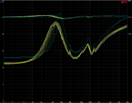
Here you can see impedance curves with VC mostly between +/-3mm. You will see 2 spikes at different resonance frequency. Thats taken at +/- 4mm excursion and Kms(x) kicks in on this particular model.
To show abit about impedance and what happens i swept a sinewave on one voice coil and measured the voltage on the other one. In the graph below basically it is the Back EMF and you can see how it actaully follows impedance because they are closely related, intimately i might say.
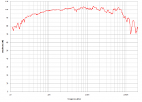
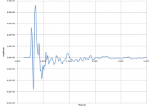
To finish for tonight the frequency response and impulse response:
Here is a zoom in also showing 30, 45 and 60 deg off axis:
<sigh> Still not in the last octave but looks promising, maybe with the other voicecoils?
Nick if the 15 incher will be used in BLH than rigid suspension is not really mandatory as i reckon you wont drive them like in the pro world. Softer suspension might be more revealing and better bass at lower level listening but you need a strong motor.
Alright some data now on the development of my 12 incher ( I know Frank's been waiting 😀 ). I started procesing the data on the reverse way i introduced it so first version tested was with the voice coil no 3.
Characteristics:
Paper former
Nominal Diameter: 50mm
Height: 5mm
Wire diameter: 0.15mm
Wire: ECW
Dual voice coil, 2 layers each.
This is the heavy voice coil, lots of copper in it. Below you can see impedance curve of one such coil.
You will notice high inductance, its the big coil (the other vcs will get lower haha) Also the disturbance around 1k. Havent figured that one yet.
An externally hosted image should be here but it was not working when we last tested it.
Fs just below 60Hz still in my good zone.
I wanted to plot Le(x) and BL(x). Le(i) and Kms(x) would be great too but i still need to find some practical solutions. Even Le(x) and BL(x) not sure how reliable they are but they are pretty close to FEMs and also similar in variations denoting the influence on each other.
I couldnt move the cone with pressure but since i had 2 voice coils i put a DC voltage on one coil and measured impedance on the other. The DC voltage will created an offset in voicecoil position so i can see it's influence on those parameters.
To adjust the voltage i made a circuit based on LM2576T-adj. Using a multiturn pot can grant you a high enough sensitivity to adjust in mV range. Schematic is the easy datasheet one.
An externally hosted image should be here but it was not working when we last tested it.
An externally hosted image should be here but it was not working when we last tested it.
Right now i got the data for +/-3.5mm excursion. Looks pretty good with the normal tilt towards the inside of the motor where fringe field is stronger. Negative values indicate position inside motor, positive values indicate position outside the motor.
An externally hosted image should be here but it was not working when we last tested it.
An externally hosted image should be here but it was not working when we last tested it.
Even tho inductance is high, delta is pretty good, advantages of underhung motors.
Because one voice coil is connected to voltage supply it will appear as shorted to the other. Here is impedance curve without supply connected but shorted.
An externally hosted image should be here but it was not working when we last tested it.
Here you can see impedance curves with VC mostly between +/-3mm. You will see 2 spikes at different resonance frequency. Thats taken at +/- 4mm excursion and Kms(x) kicks in on this particular model.
An externally hosted image should be here but it was not working when we last tested it.
To show abit about impedance and what happens i swept a sinewave on one voice coil and measured the voltage on the other one. In the graph below basically it is the Back EMF and you can see how it actaully follows impedance because they are closely related, intimately i might say.
An externally hosted image should be here but it was not working when we last tested it.
To finish for tonight the frequency response and impulse response:
An externally hosted image should be here but it was not working when we last tested it.
An externally hosted image should be here but it was not working when we last tested it.
Here is a zoom in also showing 30, 45 and 60 deg off axis:
An externally hosted image should be here but it was not working when we last tested it.
<sigh> Still not in the last octave but looks promising, maybe with the other voicecoils?
Attachments
-
 imp 1vc ac 1vc sc.png99 KB · Views: 123
 -
 impedance vs x.png142.1 KB · Views: 130
 -
 Le(x) 0Rx.png111.2 KB · Views: 139
 -
 DSC03571.jpg573.7 KB · Views: 194
 -
 BL(x) 0Rx.png110.1 KB · Views: 198
 -
 0Rx on axis.png126.9 KB · Views: 276
 -
 0Rx offaxis.png191.4 KB · Views: 257
 -
 0Rx impulse.png124.9 KB · Views: 246
 -
 0Rx impedance 1vc.png114.6 KB · Views: 233
 -
 0Rx Back Emf.png133.8 KB · Views: 246
Wow Hentai, that starting to look pretty good. That bandwidth seems stellar for a 12" driver. I think you've past diy and your in the professional realm now.
As for my little project. I'll stick to a stock suspension for now. Maybe after I've built a few I'll start to try something different.
Excellent work as usual.
Nick
As for my little project. I'll stick to a stock suspension for now. Maybe after I've built a few I'll start to try something different.
Excellent work as usual.
Nick
Hi Nick,
Thank you, I want to figure out what that 1k bumb in impedandance and back emf is, also I've looked at an IR distance sensor in order to automate the BL(x), Le(x) and Kms(x) measurements. Im not sure how precise the sensor will be because i havent found any resolution data on it but it is cheap (about 5$) HSDL-9100-021 from AVAGO. Looking at the datasheet tho, measuring from 40-50mm from the device it will have a 15-20mV slope for 10mm distance so that would be 1.5-2mV/mm so would need at least 12bit adc and/or low noise amps.
Im considering the more reliable and more expensive laser sensors, can go beyond 1k$ but have a high resolution and most can be connected straight to a RS485 line.
Stock suspension should work well. I like to take it slowly, minimize the number of variables in order to understand the behavior. After im happy with one component i move to modify/replace another or check if it allows for improvement.
Hello gents,
This is the heavy voice coil, lots of copper in it. Below you can see impedance curve of one such coil.
You will notice high inductance, its the big coil (the other vcs will get lower haha) Also the disturbance around 1k. Havent figured that one yet.
QUOTE]
Hi Hentai,
The disturbance around 1K isn't this typical for spider/surround resonance freq. ? I thought I read something in a article. Maybe I can find it if you like. Mostly there are two spikes one for the spider and one for the surround. (depends on weight and strength)
Cheers,
First off, sorry Nick I mixed up yours and Jack name, nice to have you on board Nick and Jack to of course.😱
Hentia, I agree with Nick that dose not look like a DIY speaker, you are doing a amassing job.
It is looking good I bet you will see a better high frequency respond with the low Ohm voice coil, less inductance. How much the the wizzer and cone weigh. Maybe a small suspension in the cone material close to the Wizzer help the high frequency respond.
Take care
Frank
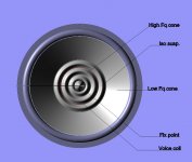
I was thinking about how to make a design without a spider, and I came up with this idea. This is inspired by the Vifa's ring radiated tweeter. I wanted to use “spider” as a part of the cone to work at high frequency and the main cone as the low frequency.
The drawing is just a sketch, just to give you an idea.
The centre is a fixed point this is where the high frequency cone is attach, is has the shape of a spider and act like one. The high and low frequency cone are isolated by a suspension that allow low frequency to travel to the large cone.
Please feel free to comment.
Take care
Frank
Attachments
Hi Hentai,
The disturbance around 1K isn't this typical for spider/surround resonance freq. ? I thought I read something in a article. Maybe I can find it if you like. Mostly there are two spikes one for the spider and one for the surround. (depends on weight and strength)
Cheers,
Hi Jef,
Indeed a posibility that needs checking.
If you find the article let me know please.
Thank you.
Hey Hentai,
Did you try and treatments on you paper cones? I just coated a piece of cold press paper with damar varnish to test it out. I also coated some with pva. Damar varnish is what the lowther crowd uses. The pva isn't as stiff as the damar. At least that's what I've read.
Just curious if you've tried any coatings.
Thanks,
Nick
Hi Nick, haven't tried any coatings yet.
Frank thats pretty neat, 2 rolls between voicecoil and phaseplug might be too much.
Frank thats pretty neat, 2 rolls between voicecoil and phaseplug might be too much.
Frank look at the altec duo-cone drivers. They are very similar to what you are trying to do. Figured they might give you some insight.
Thanks Hentai. I was just curious. I cut 4 cones this weekend. They don't look very good. And with the glue joint in them, it pulls them out of round. Im not sure if this will be a problem on not.
Not I need to buy some surrounds.
Nick
Thanks Hentai. I was just curious. I cut 4 cones this weekend. They don't look very good. And with the glue joint in them, it pulls them out of round. Im not sure if this will be a problem on not.
Not I need to buy some surrounds.
Nick
- Home
- Loudspeakers
- Multi-Way
- Project Ryu - DIY Field Coil Loudspeaker