Anatech
I have checked the probes and the component leads but it very difficult to spot any arc marks.
However I tried to reconstruct in my mind where the probe could have touched. There is a fuse holder with bare exposed terminals and the heatsink is also connected to earth which probably means that the probe connected between the heatsink, fuse, and the 3 leads of the output transistor. It could be any combination of these.
Hi Hugh,
How about we leave this open?
Normally, it is no one's business how you interact with a customer. Also, there is no way we can know all the details.

So all comments toward relating to how Hugh should handle a customer are clearly out of bounds. They can't possibly be constructive anyway.
One final comment. I know Hugh to be an honest business person. His character is not a subject for debate, steer clear of that one people!
-Chris
How about we leave this open?
Normally, it is no one's business how you interact with a customer. Also, there is no way we can know all the details.
So all comments toward relating to how Hugh should handle a customer are clearly out of bounds. They can't possibly be constructive anyway.
One final comment. I know Hugh to be an honest business person. His character is not a subject for debate, steer clear of that one people!
-Chris
But how can these things be measured?
That is difficult to answer as you might be in the clear. On my damaged ones the B - E measurement (diode test) on the DMM was lower (530-40) vs the normal 560 +- 5 on the rest of the batch.
While this pair worked perfectly by themselves , applying them to the 4 pair setup showed a problem. I ran them for a week , but with my next order , decided to replace them. The replacement pair from a totally new batch shared current within a mV of the other 3 pairs as it should.
The only difference in the pair that measured different on the DMM is that they were clicked. Logical - cause and effect. There DOES seem to be a correlation between the B-E and the current mismatch. Before I "clicked" ....all devices , even the bad ones, shared and measured the same.
OS
Hi Kenji,
An unfortunate accident, but you might be OK.
Most fatal accidents on the AKSA occur when the probe connects the output device emitters with ground. In that situation huge current is passed through the device and burns it out in microseconds as there is nothing to limit the flow.
If you inadvertently connected a probe on the top end of the fuseholder against the heatsink the fused rail shorts to earth. This spares the amp completely, but almost always blows the fuse. If the 'lumpy' earth wire between star earth and chassis is connected, and heatsinks are electrically connect to chassis also, then this destructive current may also take out the 10R resistor in the lumpy centre of the wire. (The back to back diodes and 10R resistor are at the centre of the star earth to chassis wire, and covered by heatshrink.)
Here's a tip: cover all but the last 2mm of the probes on your DMM with heatshrink so that slippage accidents do NOT occur!!
So, you should check the 5A fastblow fuse is OK, that the fuse resistor (100R) which is right in the centre of the fuse is also OK, and that the 10R resistor across the earthing diodes is undamaged. That should be all. As a general rule, if bias and offset are within spec, you have NOT damaged the outputs or drivers. It is most unusual that such an event will damage the amp, so you likely have been happy. There is strain on the rectifiers of the power supply, however, and you should check that DC voltage is 38V +/-2V and the AC component of this voltage at amp idle is not more than 300mV AC.
Chris, no objection if this thread is confined to matters technical. Kenji has suggested that with case, transformer and time investment he does NOT want his money back, but rather he wants it to run perfectly. I believe he is sincere. I will say that again; Kenji does NOT want his money back, he knows the amp can perform beautifully, and is happy with a commitment to an AKSA. Any technical advice which can be given by others here is gratefully received; I'm about done, though I now have a second wind.
I thank all those offering technical adivce for their time and expertise.
Cheers,
Hugh
I did warn you not to use those probe "sticks"
Been there, done that
I hope you will buy proper tools now
Been there, done that
I hope you will buy proper tools now
tinitus said:
Be very carefull not to touch anything, or you risk a burned amp
Use nothing else than secure and fully isolated "probes"
AKSA said:Hi Kenji,
Here's a tip: cover all but the last 2mm of the probes on your DMM with heatshrink so that slippage accidents do NOT occur!!
Hugh
Hugh,
That's a good idea, I'm going to make a set of those for special
occasions.
I get a bit nervy when there's close to 100V rails, a dozen OP
devices and you're poking around in a virtual rats nest. Whole sale
semi or even the OP and drivers can be a nightmare.
Kudos for your even handling of this thread - you certainly have
more patience than I.
cheers
Terry
 \o__o/
5A fastblow fuse is OK, that the fuse resistor (100R) which is right in the centre of the fuse is also OK, and that the 10R resistor across the earthing diodes
do I need to remove fuse to check?
the resistor 100R do i put a probe across it and measure resistance?
how do I check the back to back lumpy resistor?
if you tell me the reistance i can check by putting the DMM across it.
thanks
Hi Kenji,
You can normally tell if a fuse is OK; the wire within will be clearly broken ('fused'). But you can easily remove it to check with a DMM.
With power off for at least two hours, yes, you can use a DMM on low resistance (200R range) to check the fuse resistor. It should be 100R +/-10R.
The 'lumpy' wire resistor is 10R, and can be check with a DMM by removing one end and checking for resistance across it.
I hope this helps!
Cheers,
Hugh
tinitus said:I did warn you not to use those probe "sticks"
Been there, done that
I hope you will buy proper tools now
tinnitus it appears your email via this site is disabled. Is there a way I can contact you privately?
cheers.
expensive click
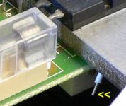
To avoid 'expensive clicks' you can use clip-on probes
like the ones shown in the picture.
Usually i decide what i want to measure before applying power,
and attach the clip-ons before applying power.
For adjusting bias/offset i use the screwdriver shown at the bottom of the picture, insulated with heatshrink.

Looking at the picture of your amplifier after rewiring, apparently you have failed to comprehend the advice about lead dress given to you previously.
Sofar you didnt manage to exclude even one possible cause of the (subjective) erratic behavior of your amp.
In fact , the probe slipping made you move into the opposite direction, introducing yet another variable.
Since you already have been given excellent advice by people i regard highly in terms of technical knowledge AND helpfulness,
i can only advise you to work methodically, step by step, to exclude potential causes of your amp's erratic behavior.
If you don't feel confident enough to do this yourself, find a qualified (audio)electronics-technician to do this for you.
Good luck,
Klaas
To avoid 'expensive clicks' you can use clip-on probes
like the ones shown in the picture.
Usually i decide what i want to measure before applying power,
and attach the clip-ons before applying power.
For adjusting bias/offset i use the screwdriver shown at the bottom of the picture, insulated with heatshrink.
Looking at the picture of your amplifier after rewiring, apparently you have failed to comprehend the advice about lead dress given to you previously.
Sofar you didnt manage to exclude even one possible cause of the (subjective) erratic behavior of your amp.
In fact , the probe slipping made you move into the opposite direction, introducing yet another variable.
Since you already have been given excellent advice by people i regard highly in terms of technical knowledge AND helpfulness,
i can only advise you to work methodically, step by step, to exclude potential causes of your amp's erratic behavior.
If you don't feel confident enough to do this yourself, find a qualified (audio)electronics-technician to do this for you.
Good luck,
Klaas
klaas,
why do you feel that my lead dress is wrong after the rewiring?
please explain. It doesnt help me to be criticised without explaining how to fix it.
Thanks.
why do you feel that my lead dress is wrong after the rewiring?
please explain. It doesnt help me to be criticised without explaining how to fix it.
Thanks.
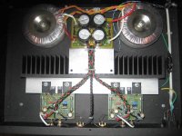
I still think the layout is wrong as there has been plenty of examples given with the amp modules at the back close to the signal inputs and power supply at the front so there is less chance of interaction.
By doing that you eliminate one variable and have less chance of hum as well.
While you have signal, speaker and power wires all together plus a power supply between RCA inputs there's a strong chance of pickup...... hummmmmmm.
By doing that you eliminate one variable and have less chance of hum as well.
While you have signal, speaker and power wires all together plus a power supply between RCA inputs there's a strong chance of pickup...... hummmmmmm.
rabbitz said:I still think the layout is wrong as there has been plenty of examples given with the amp modules at the back close to the signal inputs and power supply at the front so there is less chance of interaction.
By doing that you eliminate one variable and have less chance of hum as well.
While you have signal, speaker and power wires all together plus a power supply between RCA inputs there's a strong chance of pickup...... hummmmmmm.
As I said before this particular layout was suggested to me by Hugh. Hugh himself used this layout for one amp he made. Its the only one which will fit for this 2U case. Your suggestion will not fit into a 2U case.
But Klaas is talking about lead dress. ITs not so much the layout he is criticising.

Here's one built by a friend in a 2U case
That's a work of art, craftsmanship of the highest order.
John
Hi John,
That is true, but a great project begins with a good layout. Once the basics are understood, a layout will generally present itself after a few attempts.
I don't think there are many of us that simply do a great job in the first try. It takes some research and planning. There is the difference between someone who doesn't plan and gets mediocre results, and someone who does plan and gets excellent results.
-Chris
Personally I would try avoid placing supply board in between trafos
May not matter, but you never know
Though I suppose it could be rated as a well proven layout
Most impportant would be to get signal input lines away from supply
And thats achieved 100% by such layout
But twisting cables is not my kind of thing
I prefer them to not even touch each other
But thats not the issue here
Some say the diodes(bridge) are noisy, and their connections
I dont know about that, but try to follow such claims, just in case
- Status
- Not open for further replies.
- Home
- Amplifiers
- Solid State
- Professor smith needs help