I remember the sound of a new Porsche I heard some time ago, very well actually, VERY smooth 😎
My friends stereo, nothing is stored at all, I guess theres nothing to remember
Smith, you dont listen, why so complicated
Have your B1 checked with scope
If its in the clear, have your Aksa checked same way
Or else you need to try other amps and preamps, to see if they are different
You got those advice several times
Im sure you will find something, one way or the other
To keep talking doesnt help any more
The other day I found a connection on my right channel speaker crossover that wasnt soldered at all
Leads were touching, prepared fore soldering, just forgot the soldering
I had been listening to that fore a couple of days
Professor smith said:
A bad joint would cause a big resistance on the DMM right?
Sometimes, but not always.
Find somebody to do it proper.
Magura 🙂
Hi Professor smith,
I see you are surrounded by some very talented people here attempting to assist you with your problem. Hunt down a bunch of posts over time from some of these people. You have incredible talent at your disposal. All you need to do now is start troubleshooting fresh and listen to this assembly of experts.
You did PM me, saying you had posted pictures of your amplifier wiring. Can you please point them out to me? I can't seem to find them. If you are having trouble, send the pictures to me and I'll post them for you. That way we can all be on the same page to help you out.
Last point. Electronics is a small part of the study of Physics, a science. That means that we are dealing with facts backed up by laws and equations that may accurately describe how a circuit will behave. Of course, we will be dealing with first or second order approximations to cut down the total number of interactions. That means that we will be dealing with the most likely causes and interactions, and these have exactly zero to do with what we wish would occur. Circuits behave in accordance with the laws of physics, so an error can not be debated. Things either are, or are not working as designed.
Since we can not directly see the movement of electrons, some test equipment will be required. That means a good multimeter and an oscilloscope at the minimum, plus an audio oscillator of some description. Fact: a cheap multimeter will lie to you. If you are skilled in math, work out the error tolerances and apply that to your readings to understand the uncertainty of your readings. Yeah. It's boring as heck, but I had to do it professionally. The results are quite illuminating. Often, the last digit on a cheap multimeter should be ignored, even the second last digit may have an uncertainty of a few counts. How's that for trustworthy measurements?
I say this because a poor solder joint may only show up reliably when using a Kelvin connection (4 wire ohms). You need a very good bench meter (eg. HP 3457A or better, a 34401A is iffy). Keithly does manufacture meters capable of this, as does Agilent in the 3458A. These are meters over $3,000 USD. You are not using one from what I have read so far. Any other meter will most likely read a bad connection as being fine (as Magura pointed out).
Soldering is a skill not everyone has.
-Chris
Member
Joined 2009
Paid Member
From the description of the problem, can you suggest where the bad solder joint might be ? At least one option is to warm it over with an iron ?
Hi Gareth,
Anything said before we can see what the wiring looks like is a complete guess and a waste of everyone's time.
Any bad solder joints that may exist are only going to be one of a few problems from what I have seen of the B1 pictures. We don't even have any traces from an oscilloscope to look at. We have .... nothing. Nothing to go on at all.
Another rule of troubleshooting. Never change anything on a global scale until you actually find and fix your problems first. If you do, the chances are high that more problems will be created and evidence that may have helped troubleshoot will be destroyed.
When I see evidence that many things were done in order to find a problem without a methodical line of thinking, I know fault finding will be difficult. This is called "struck by technician", a technician in panic mode is a dangerous thing. Extra charges apply and all bets are off.
-Chris
No.From the description of the problem, can you suggest where the bad solder joint might be ?
Anything said before we can see what the wiring looks like is a complete guess and a waste of everyone's time.
Any bad solder joints that may exist are only going to be one of a few problems from what I have seen of the B1 pictures. We don't even have any traces from an oscilloscope to look at. We have .... nothing. Nothing to go on at all.
Another rule of troubleshooting. Never change anything on a global scale until you actually find and fix your problems first. If you do, the chances are high that more problems will be created and evidence that may have helped troubleshoot will be destroyed.
When I see evidence that many things were done in order to find a problem without a methodical line of thinking, I know fault finding will be difficult. This is called "struck by technician", a technician in panic mode is a dangerous thing. Extra charges apply and all bets are off.
-Chris
Member
Joined 2009
Paid Member
B1 - is the preamp ?
Can the AKSA amp be removed from the system, replace with a different amp. B1 stays in place. See if you can reproduce the problem with a different amplifier, one that Kenji knows to be reliable. This tests the theory that the problem is in the pre-amp without the added variable of the new AKSA amp.
Can the AKSA amp be removed from the system, replace with a different amp. B1 stays in place. See if you can reproduce the problem with a different amplifier, one that Kenji knows to be reliable. This tests the theory that the problem is in the pre-amp without the added variable of the new AKSA amp.
Hi Gareth,
It should have been made on a PCB by unskilled (new) DIYer's, or at least perf board. It can be constructed by point to point methods if the builder is experienced.
To begin trying different things right now will only confuse the situation. It's very important that we see what the condition of the amplifier is. Then, some basic testing on a service bench would be in order. We need to know facts more than anything else right now.
This is one thing I was attempting to point out when I mentioned that a debate or discussion would not change the facts (rephrased). Get the facts and follow the evidence. This will allow Kenji to solve the issues here. Premature discussion is a complete waste of time.
-Chris
Yes. One of Nelson Pass' designs.B1 - is the preamp ?
It should have been made on a PCB by unskilled (new) DIYer's, or at least perf board. It can be constructed by point to point methods if the builder is experienced.
There is no theory that the preamp is the problem. I am convinced that there is more than one problem in that system, but that is my personal guess only. Right now there is no proof of anything.This tests the theory that the problem is in the pre-amp without the added variable of the new AKSA amp.
To begin trying different things right now will only confuse the situation. It's very important that we see what the condition of the amplifier is. Then, some basic testing on a service bench would be in order. We need to know facts more than anything else right now.
This is one thing I was attempting to point out when I mentioned that a debate or discussion would not change the facts (rephrased). Get the facts and follow the evidence. This will allow Kenji to solve the issues here. Premature discussion is a complete waste of time.
-Chris
Thanks Chris, Gareth,
Following this closely; it is good to have another tech look this over.
Cheers,
Hugh
Following this closely; it is good to have another tech look this over.
Cheers,
Hugh
anatech said:Hi Gareth,
No.
Anything said before we can see what the wiring looks like is a complete guess and a waste of everyone's time.
Any bad solder joints that may exist are only going to be one of a few problems from what I have seen of the B1 pictures. We don't even have any traces from an oscilloscope to look at. We have .... nothing. Nothing to go on at all.
Another rule of troubleshooting. Never change anything on a global scale until you actually find and fix your problems first. If you do, the chances are high that more problems will be created and evidence that may have helped troubleshoot will be destroyed.
When I see evidence that many things were done in order to find a problem without a methodical line of thinking, I know fault finding will be difficult. This is called "struck by technician", a technician in panic mode is a dangerous thing. Extra charges apply and all bets are off.
-Chris
The thing is how can Magura say the soldering is poor when he hasnt seen it??
None of my pictures are that detailed to show it up close. But what I will do is take another picture and this time it will be more detailed showing the soldering.
The trouble is, what if it turns out that the problem is all in the mind as someone suggested? or if it is a 'burn in' issue? None of these things can be proven.
This is not a serious problem though because the offset and the bias are not extremely out of range. It plays music fine and it even does it very well at times so looking at it positively I doubt there is anything seriously wrong. Is this reasonable?
Also the B1 buffer has nothing to do with this. I am not using it in my system at all.
They are not 100% accurate but how do you know they are lying?
If we ignore the last digit on the mv setting that is a very small error of 9mv. So if we are measuring offset or bias, they can vary by this amount anyway.
This is not a serious problem though because the offset and the bias are not extremely out of range. It plays music fine and it even does it very well at times so looking at it positively I doubt there is anything seriously wrong. Is this reasonable?
Also the B1 buffer has nothing to do with this. I am not using it in my system at all.
Fact: a cheap multimeter will lie to you. If you are skilled in math, work out the error tolerances and apply that to your readings to understand the uncertainty of your readings. Yeah. It's boring as heck, but I had to do it professionally. The results are quite illuminating. Often, the last digit on a cheap multimeter should be ignored, even the second last digit may have an uncertainty of a few counts. How's that for trustworthy measurements?
They are not 100% accurate but how do you know they are lying?
If we ignore the last digit on the mv setting that is a very small error of 9mv. So if we are measuring offset or bias, they can vary by this amount anyway.
Kenji,
See if you can borrow a quality power filter. It is possible the mains is quite dirty as you live in London where there is huge, unpredictable industrial demand on the grid.
I have had instances in Melbourne where such a filter completely cured the unpredictable sound quality you are experiencing.
Hugh
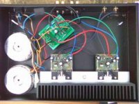
chris sent me an email telling me that oscillation of the amp can occur due to improper wiring positioning. AKSA, can you tell me whether this is the case with the AKSA?
I knew that wires can 'couple' but I didnt know it was that significant.
The other thing with this amp is that if you look at my picture, the power wires and signal wires are next to each other and I dont see how I would be able to separate them further.
I knew that wires can 'couple' but I didnt know it was that significant.
The other thing with this amp is that if you look at my picture, the power wires and signal wires are next to each other and I dont see how I would be able to separate them further.
For wiring have a look at the pictures I sent you of the layout on my AKSAs. Power supply at the front and amp modules at the back. That way no signal or speaker wires are near AC or DC wiring. In addition, twist and twist the wires.
Chris, is the photo of this amp the one tinitus posted in post 384, by chance?
Prof, even though Hugh assembled the boards, heat sinking into the traces when the connections were being made may have created a cold joint on a component. Look for dull, almost crystalline appearance (although not always this obvious). This can certainly cause intermittently variable performance.
Stuey
I think it is better to twist the speaker return with it's respective flow until it reaches the PCB and then the speaker return follows the Power twisted triplet to the main Audio Ground.
I surprised that some AKSA owners haven't chimed in with their thoughts. I imagine they aren't willing to admit to cap burn in for fear of ridicule. I think this would have been better discussed at AC on Hugh's forum as there are a lot of experienced AKSA builders who would have firstly provided reassurance to ease your concerns.
If burn in is the issue then it will all be over by mid June and the cycles should be getting shorter now as those who have actually bought the genuine N+ would know. It's well documented at Hugh's forum (if you can access it as AC disappeared for a while and now can't unless you join) and is mentioned in his superb instructions.
There has been plenty of good advice given by plenty of non AKSA owners but it has to be remembered that this is a kit and in this case a working module and not a posted design that might need some special skills and equipment. The AKSA used to be sold as an amp you can build on your kitchen table (and it is) and Hugh lists the tools you need and as such you do not need oscilloscopes plus 3 years of electrical training. All it needs is to follow the instructions step by step, some patience and very basic electronic skills.
Hugh has great build instructions plus a comprehensive diagnostics section with the kits but not sure if it's supplied with the modules. It has checks and voltage reference points that would cover 99% of issues. I had a problem (self inflicted) with an AKSA years ago and 30 minutes with Hugh's diagnostics and DMM and I knew what the problem was and I'm no amp guy. Actually I hate them and not interested in their workings as I find it boring. That's why I buy from Hugh as I want a solid mature design with little brain input on my behalf.
Unlike most of Hugh's customers who have taken a leap of faith, trust and believe the designer, Prof for some reason has not and doing so is making it so much more difficult for himself. Unfortunatley it's been treated as a car with a problem and the service manager tells you they all do that and will be OK in 10k.... do you believe him?
Hugh is remarkable in his knowledge and each time I received an answer he has been right again and again.
Sure Prof's build is not the best but hey I've seen worse so doesn't deserve a rib about it. One thing you must do Prof is take some of the advice that has been given in this thread onboard and follow through but how much depends on how far you persue this hobby. Building kits is different to posted designs which is different to designing but you need the appropriate skill levels for the chosen stage.
I really hope this works out for the best as it is a great amplifier ..... "patience young Luke".
Stuey said:Chris, is the photo of this amp the one tinitus posted in post 384, by chance?
Stuey
No that's the pic of my build I sent to Prof as an example layout. BTW, that amp was dead quiet with no hums, buzzes and farts (and no Blackgate).
rabbitz said:
No that's the pic of my build I sent to Prof as an example layout. BTW, that amp was dead quiet with no hums, buzzes and farts (and no Blackgate).
Are you sure 😕
Just to make clear if there have been a misunderstanding
http://www.sendspace.com/file/man8b3
This link is with bigger pictures, scoll down at bottom
Attachments
Whoops 
Tinitus you are on the ball and correct. Sorry, my error.
The pic in post #431 is not the amp being discussed. See posts #384 #436.
Maybe moderators can give my pic from post #431 the flick to save any confusion.
Tinitus you are on the ball and correct. Sorry, my error.
The pic in post #431 is not the amp being discussed. See posts #384 #436.
Maybe moderators can give my pic from post #431 the flick to save any confusion.
Hi rabbitz,
1. If this was a kit sold with case, wires and a wiring guide I might agree with you more. It isn't, and Hugh has no control over what wire is used, or it's placement within the chassis.
2. If the kit was working properly, and the wiring was done properly, there would be no need to check further.
3. If this builder had experience and knowledge doing previous successful amplifier builds, and this one worked properly, there would be no need to check further.
4. When kits distributed by Heathkit (as one example) failed to function properly, they were returned to the factory or closest store. There, a trained technician with a full bench would troubleshoot and repair the problem(s).
5. Your statement is really about what you can get away with, not at all what should be done.
All warranty repair shops must test the repaired item to spec. before it is released. In audio, that means we need to have the training and equipment to check the proper operation of everything we repair. That's whether or not we work in an area that could be thought to affect the performance of the repair item.
Any time the wiring of an amplifier is disturbed (wiring it up would really count as disturbing the wiring!), the performance needs to be confirmed. Certainly any time you work in an amplifier circuit, the performance needs to be confirmed.
-Chris
Although I have great respect for your knowledge and abilities, I find I have to disagree with you on these points. And this is why ...The AKSA used to be sold as an amp you can build on your kitchen table (and it is) and Hugh lists the tools you need and as such you do not need oscilloscopes plus 3 years of electrical training.
1. If this was a kit sold with case, wires and a wiring guide I might agree with you more. It isn't, and Hugh has no control over what wire is used, or it's placement within the chassis.
2. If the kit was working properly, and the wiring was done properly, there would be no need to check further.
3. If this builder had experience and knowledge doing previous successful amplifier builds, and this one worked properly, there would be no need to check further.
4. When kits distributed by Heathkit (as one example) failed to function properly, they were returned to the factory or closest store. There, a trained technician with a full bench would troubleshoot and repair the problem(s).
5. Your statement is really about what you can get away with, not at all what should be done.
All warranty repair shops must test the repaired item to spec. before it is released. In audio, that means we need to have the training and equipment to check the proper operation of everything we repair. That's whether or not we work in an area that could be thought to affect the performance of the repair item.
Any time the wiring of an amplifier is disturbed (wiring it up would really count as disturbing the wiring!), the performance needs to be confirmed. Certainly any time you work in an amplifier circuit, the performance needs to be confirmed.
-Chris
- Status
- Not open for further replies.
- Home
- Amplifiers
- Solid State
- Professor smith needs help