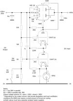
I would lower R14 to possibly 330K maybe even 220K, but connect EF80 in pentode mode, this will lower the output impedance of the supply also.
What's U7 for?
U7 is the pass tube, it handles most of the work load.
This thread makes me want to learn about regulators... Say I have 350VDC and I want 300VDC regulated and I have a 6N2P for the error voltage, a VR tube for the reference, and a 6080 for the pass device. How would that look schematic wise?
Or say I want a regulated 300VDC power supply for up to 1A of current. What then? Several 6080's in parallel would work but would be such a waste IMHO. A MOSFET would be better in this case? Could I use an NE-2 at the VR reference?
Explain it like I'm 5 years old if you care to.
I don’t think you will have enough voltage swing to drive the 6080 grid without configuring it in a cascode, the cathode coupled design wouldn’t have enough gain.
Attachments
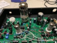
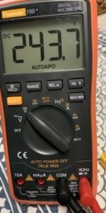
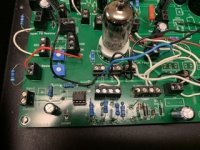
I took your basic setup and did some prototyping, except I’m using a 6080 pass a EF86 For control tube and a 12AT7 for the error amp. Works nicely so far, very similar to my spice simulation. My voltage reference and voltage divider are a little different.