The Q1 have been replaced and voltage on C9 is 404Vdc.So with lower output no hum. Perhaps the voltage on C9 is to low, bad Q1 ?
Mona
If all else fails i can design you a board for the attached schematic. I haven't filled out all the values, because some are TBD.
The ECC82 is operating outside its heater to cathode voltage in your supply.
Thanks, thats a possibility yes. But I`m beginning to get so tired of this preamp so I have to get it fixed and try to sell it. Noone will buy a preamp thats not original anymore.
Thanks. It is my own design (after reading many literature).Thats a very good schematic, Alternatively you could remove the decoupling on the EF80's G2 and run a high value resistor from the raw B+ to G2 of the EF80. In that way you could reduce output ripple.
Do you think to remove R12, and use only R4 in my schematic? I supply VT3 through them (and also G2).
I use EF80, because I have them a lot lot lot 🙂 But also EF184 is common in my stock, so if I will return to this project once, I can try.Have you seen my comment about CCS loading the EF80? this is something to consider, cause you can get up to an order of magnitude higher amplification from the EF80 that way. The EF184 is pin compatible by the way and has slightly higher Mu then EF80.
I read about CCS, do you have any hints how to? Thanks
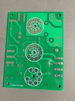
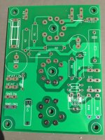
I have already finished my PCB some years ago, but not using a lot, cause I still missing some enclosure (and without it, as you know, hum occur). But I glad to look on the other way how to design simple and effective regulator 😉PS if all else fails, i could help you cook up a new PCB for the Phono amp, that uses a simpler yet effective regulator.
Beacuse we want? 🙂1) why would you use vacuum diodes in the 21st Century? 😕
I used not only common EZ8x, GZ34,... but I am successful also with rectifiers like PY88, 6c10p, etc.... btw. 6c10p is very nice choice for e.g. EL84 PP...
It's not the heater-cathode voltage out of range (is only about 35V here) but the currents in the ECC82 are much to low.Thanks, thats a possibility yes. But I`m beginning to get so tired of this preamp so I have to get it fixed and try to sell it. Noone will buy a preamp thats not original anymore.
Try with a ECC83 (12AX7) not optimal but much closer.
Mona
Cascade filtered power supply.
And now from our sponsors... New! Improved!
GoatGuy
And now from our sponsors... New! Improved!
GoatGuy
Attachments

Last edited:
The schematic does not reflect the PCB. As Ketje wrote, the PCB is for an E88CC (ecc88, 6DJ8,6N23S) heater wiring. An ECC82 will get only half of its heater voltage thus the hum.I see the print is for E88CC. If you put in a 12AU7 there is a problem with the heater.
On pins 4 and 5 the 12AU7 expect 12,6V.Here it gets 6,3V and it puts the middle of the heater circuit on ground on pin9. Pin9 is only a screen in the E88CC, no connetion to the heater.
Did you try one of the above tubes? Did the schematic came with the pre-amp? I would be surprised.
The schematic does not reflect the PCB. As Ketje wrote, the PCB is for an E88CC (ecc88, 6DJ8,6N23S) heater wiring. An ECC82 will get only half of its heater voltage thus the hum.
Did you try one of the above tubes? Did the schematic came with the pre-amp? I would be surprised.
Excuse me for saying, but does any of you guys bother to read the whole tread.
The pcb was initially made for ECC88 but Wall changed it to ECC82. So I did too. But as said in #36 the heater is now made for ECC82. IF you care to help, please don't be hung up in all kinds of chit chat about things that have nothing to do with the problem itself.The schematic is made by me and it's absolutely correct drawn.
Thats a very good schematic, Alternatively you could remove the decoupling on the EF80's G2 and run a high value resistor from the raw B+ to G2 of the EF80. In that way you could reduce output ripple.
Have you seen my comment about CCS loading the EF80? this is something to consider, cause you can get up to an order of magnitude higher amplification from the EF80 that way. The EF184 is pin compatible by the way and has slightly higher Mu then EF80.
PS if all else fails, i could help you cook up a new PCB for the Phono amp, that uses a simpler yet effective regulator.
I want to re-design and improve schematic from post
https://www.diyaudio.com/forums/tubes-valves/348318-tube-regulator.html#post6050633
any sugestions? I need at the output +200V. Probably I will try EF184, and supplu G2 of pentode from B+ before regulator.
Thanks.
Thanks, thats a possibility yes. But I`m beginning to get so tired of this preamp so I have to get it fixed and try to sell it. Noone will buy a preamp thats not original anymore.
Not true! It could be IMPROVED. 😀
I want to re-design and improve schematic from post
https://www.diyaudio.com/forums/tubes-valves/348318-tube-regulator.html#post6050633
any sugestions? I need at the output +200V. Probably I will try EF184, and supplu G2 of pentode from B+ before regulator.
Thanks.
You could order some of these boards if you want, I will post gerbers if you need them.
Attachments
That's the one I have too right? works great and it will most likely end up in my preamp once I get to it
Excuse me for saying, but does any of you guys bother to read the whole tread.
The pcb was initially made for ECC88 but Wall changed it to ECC82. So I did too. But as said in #36 the heater is now made for ECC82. IF you care to help, please don't be hung up in all kinds of chit chat about things that have nothing to do with the problem itself.The schematic is made by me and it's absolutely correct drawn.
OK, if the schematic reflects the circuit board correctly (after adaptation for the ECC82 heater was done), than it's a very weird design (maybe a faulty circuit board?).
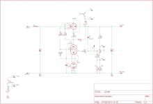
The 6C19P is biased positive by R14 (the connection to the internal screening of the EF80 doesn't influence the bias of the 6C19P). So it will just pass current.
The EF80 is connected as a triode, in which g2 functions as the anode (g3 and plate are connected to the cathode).
The ECC82 is not controling the 6C19P but only the EF80 (because control via the connection from the outer screening of the EF80 to the grid of the 6C19P is not possible).
So it looks to me that the EF80 could only be functioning as a kind of ripple killer. I find it hard to see how you can adjust the output voltage with R16. It will influence the amount of current flowing through the EF80, but so very little that it can hardly inluence the output voltage.
I looked a bit if the circuit board was maybe made for another tube than the EF80, but I couldn't find something in this direction.
Last edited:
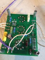
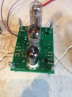
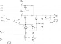
Got problems with this rectifier and regulator unit. It puts out some 100hz ripple that causes hum in the preamp. It uses an EZ80 as rectifier, 6C19P as power element, EF80 as error amplifier and a 12AU7 as reference. If I remove the 12AU7 reference tube the 100hz ripple is gone and no hum. Of course, the voltage drops to about 200Vdc. I know, some of you will find this circuit a bit strange but this is what the manufacturer has done. But clearly, something is wrong.
You would get rid of nearly all the hum if you bypass R15 maybe at least a 4.7uf
Use a low pass filter for a cleaner reference to the 12AU7, and connect the screen grid of the EF80 to a voltage divider between the 67K and the cathode reference Zener. Probably a 47K and 10K connect the screen between these two, much more gain and better regulation from the EF80. Before the regulation was about 0.1%(triode connected), with more gain you would get closer to 0.01%
One might even use a 12AT7 instead of 12AU7, giving more gain in the error amp.
Attachments
Last edited:
If A1008 is still here, try put a 68k between C8 and C9.
It's no solution for the problem but could be a cure for the hum.
Mona
It's no solution for the problem but could be a cure for the hum.
Mona
If I dont get it fixed its useless, Tube Snobbery or not. The Wall company wont help so I`m running out of options.
I'm not surprised. Tell me you didn't pay almost $7,000 for that PoS. I have never seen such a foxed up design. ( I really should have gotten into audiophool grifting as a profession. 😀 )
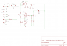
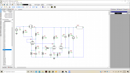
In the first place, a 56uF reservoir capacitor is too large for a hollow state diode. The Isurge rating is quite low as compared to solid state diodes and it's all too easy to bust that spec. A hollow state power supply needs a smaller reservoir and an LC low pass filter.
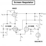
The active regulator looks overly complicated and makes no sense. It also doesn't have a stable voltage reference, and so won't perform very well. I'd scrap the whole damn thing and start over. Reduce the reservoir to about 34uF (two 68uF/350V capacitors in series with voltage balancing resistors) a 10H filter choke and a 220uF capacitor behind the choke, and a simpler, but more effective, active regulator. I did this design (attached) for the Le Renard project as a screen voltage regulator. The 6AQ5 is over rated for this application, so may work just fine for a preamp. You could use one or more 6AS7s for the series pass device if you need moreamps.
Attachments
- Home
- Amplifiers
- Tubes / Valves
- Problem with tube regulator