What values for R15, R16 and D5 will you suggest for 250Vdc out on your schematic at #5?This is more like it. But with the resistors (440k-51k) and zener (33V) the output is more or less ~330V.
Mona
Got problems with this rectifier and regulator unit. It puts out some 100hz ripple that causes hum in the preamp. It uses an EZ80 as rectifier, 6C19P as power element, EF80 as error amplifier and a 12AU7 as reference. If I remove the 12AU7 reference tube the 100hz ripple is gone and no hum. Of course, the voltage drops to about 200Vdc. I know, some of you will find this circuit a bit strange but this is what the manufacturer has done. But clearly, something is wrong.
1) why would you use vacuum diodes in the 21st Century? 😕
2) in any case, you are killing any "tube goodness" it "might" impart to the rest of the circuit, by regulating after it.
3) 1+2 make me think of tube snobbery and no real advancement or improvement.
4) you might use Q1 as regulator so everything to is right is unneeded.
5) and in any case it works *wrong* 🙄
Thats why I hoped for some help from the community here. The schematic is from a Wall Audio Opus 100 Sym preamplifier and this is how this Andreas Wall has made it. And its humming. Wrong or not.
As you can see at #17 ,keeping R15 440k and D5 33V, R16=68k for 250V out and 75k for 230V.What values for R15, R16 and D5 will you suggest for 250Vdc out on your schematic at #5?
Mona
Oh. now I get it.
Who cares the circuit makes sense, it works properly or the preamp hums?
It´s an **Audiophile** product and the only relevant parameter is its price tag:
Wall Audio OPUS 100 SYM Pre Amplifier | highend-electronics, inc.
I suggest not repairing it or it will lose serious Mojo.
Did I detect "Tube Snobbery" (as opposed to Tube *design*) when I first read about its problems and saw the schematic?
Maybe I was not far off.
Who cares the circuit makes sense, it works properly or the preamp hums?
It´s an **Audiophile** product and the only relevant parameter is its price tag:
🙄$6,960.00 USD
Wall Audio OPUS 100 SYM Pre Amplifier | highend-electronics, inc.
I suggest not repairing it or it will lose serious Mojo.
Did I detect "Tube Snobbery" (as opposed to Tube *design*) when I first read about its problems and saw the schematic?
Maybe I was not far off.
Oh. now I get it.
Who cares the circuit makes sense, it works properly or the preamp hums?
It´s an **Audiophile** product and the only relevant parameter is its price tag:
🙄
Wall Audio OPUS 100 SYM Pre Amplifier | highend-electronics, inc.
I suggest not repairing it or it will lose serious Mojo.
Did I detect "Tube Snobbery" (as opposed to Tube *design*) when I first read about its problems and saw the schematic?
Maybe I was not far off.
If I dont get it fixed its useless, Tube Snobbery or not. The Wall company wont help so I`m running out of options.
Are you telling us that Wall Audio have sold something for $6500 andIf I dont get it fixed its useless, Tube Snobbery or not. The Wall company wont help so I`m running out of options.
in addition refuses to help with support ??? That must be a record of negligence!
Scrap the so called regulator and replace with something decent.As a preamp
it works ( i hope ) in class-A thus consuming an steady amount of current.
If so you can replace the regulator with some resistors and caps .
Or design a new board yourself, i take its a PBC? If so you could send me the mechanical drawings for a pcb and i will design you a regulator that fits.
Also, pics would be helpfull.
Also, pics would be helpfull.
Are you telling us that Wall Audio have sold something for $6500 and
in addition refuses to help with support ??? That must be a record of negligence!
Have been sending these two email but no reply.
Scrap the so called regulator and replace with something decent.As a preamp
it works ( i hope ) in class-A thus consuming an steady amount of current.
If so you can replace the regulator with some resistors and caps .
Or design a new board yourself, i take its a PBC? If so you could send me the mechanical drawings for a pcb and i will design you a regulator that fits.
Also, pics would be helpfull.
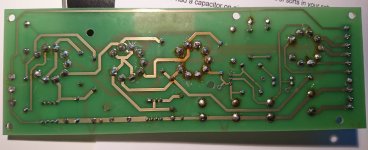
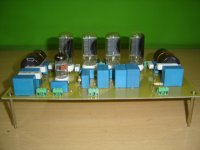
Pic of the regulator board. I`ll messure them in a short time. The board is 205 x 70 mm.
Attachments

Last edited:
1) why would you use vacuum diodes in the 21st Century?
Me too‼
Attachments

I just checked PCB manufacturers in China, five of those boards lead-free ENIG runs about €42.
I'm thinking CRCRC filtering into a 6C19P regulator, EF184 current source loaded, 85A2 reference.
Ive assumed 75mA load for the regulator in my calculations.
310VAC solid state rectified, into 220uF will give you about 420V loaded. the CRCRC filter can knock off around 20V two cascaded 100R/47uF filter stages drop off 15V under 75mA load. leaving you with ~400VDC at 200mV RMS ripple on the input of the regulator, taking -10% mains into account the input of the regulator is about 360V. At 250V out, the 6C19P sees 110V. at high mains the 6C19P sees 190V. Both are within the datasheet limits for VA max. however the anode dissipation of 14.25W isn't.
The 85A2 un-bypassed reference self noise is about 60uV (30-10.000 Hz), this will be amplified ~3x leaving you with 180uV self noise.
I'd say 0.5mV noise should be achievable with a more conservative circuit, and CRCRC filtering. On the input.
I see the print is for E88CC. If you put in a 12AU7 there is a problem with the heater.
On pins 4 and 5 the 12AU7 expect 12,6V.Here it gets 6,3V and it puts the middle of the heater circuit on ground on pin9. Pin9 is only a screen in the E88CC, no connetion to the heater.
The color code on the so called 51k resistor doesn't look like green-brown-orange ?
Mona
On pins 4 and 5 the 12AU7 expect 12,6V.Here it gets 6,3V and it puts the middle of the heater circuit on ground on pin9. Pin9 is only a screen in the E88CC, no connetion to the heater.
The color code on the so called 51k resistor doesn't look like green-brown-orange ?
Mona
I see the print is for E88CC. If you put in a 12AU7 there is a problem with the heater.
On pins 4 and 5 the 12AU7 expect 12,6V.Here it gets 6,3V and it puts the middle of the heater circuit on ground on pin9. Pin9 is only a screen in the E88CC, no connetion to the heater.
The color code on the so called 51k resistor doesn't look like green-brown-orange ?
Mona
This one original had ECC88 but now Wall is using ECC82. I was told by another "tubeguru"
 to swap to ECC82 to see if that would help. So I did,
  but it didnt help. But if you check the schematic you see the heater thing is taken care of. And you are right, the so called 51k is a 56k resistor.
Last edited:
The heater is ok on the schematic but the print shows different.The two heater traces from the EF80 (6,3V) are going to pin 4 and 5 of the E88CC socket witch is wrong for the 12AU7.
Since pin 9 is on ground for the E88CC you get a connection of the heater circuit via the 12AU7.And that could give a hum problem (depends on the rest of the heater circuit).
Mona
Since pin 9 is on ground for the E88CC you get a connection of the heater circuit via the 12AU7.And that could give a hum problem (depends on the rest of the heater circuit).
Mona
The heater is ok on the schematic but the print shows different.The two heater traces from the EF80 (6,3V) are going to pin 4 and 5 of the E88CC socket witch is wrong for the 12AU7.
Since pin 9 is on ground for the E88CC you get a connection of the heater circuit via the 12AU7.And that could give a hum problem (depends on the rest of the heater circuit).
Mona
Mona, I appreciate your concern, 🙂 but believe me its been fixed.
Thanks, but the print shows different and why this "Any idea why the ripple and hum is gone when removing the ECC82 tube? " if the , by the ECC82, grounded heater isn't there ?Mona, I appreciate your concern, 🙂 but believe me its been fixed.
Mona
Thanks, but the print shows different and why this "Any idea why the ripple and hum is gone when removing the ECC82 tube? " if the , by the ECC82, grounded heater isn't there ?
Mona
The pic of the pcb was taken before the heater was adapted for the ECC82 tube. The ripple and hum disappeared when the pcb was set for the ECC88 and also when the pcb was set for the ECC82. In both cases the ripple and hum disappeared when the tube was removed.
- Home
- Amplifiers
- Tubes / Valves
- Problem with tube regulator