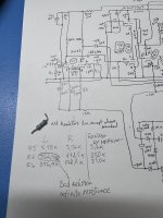
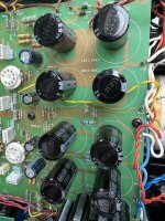
Thank you very much Chris! Tomorrow evening I have free time and will check theses. Will let you know later. Good night! (in my local zone)This amp has two important gain-setting feedbacks. The first is the input diff stage's degeneration resistor (10K Ohm). These need to be pretty close to the same for each channel. The second is the ratio of the three-in-series 39K resistors to the 3K9 cathode resistors that they're feeding. These need to be as close as possible to "the same" for all four ratios. I'd look hard at the 39K resistors because they've been running the warmest.
All good fortune,
Chris
All of these ratios, voltage, current, and power, are about 1dB. This is the ratio expressed on a log scale, because we humans' sensory inputs are not linear, but rather are (roughly) logarithmic. A Bel is a power ratio of 10, so a deciBel is a tenth of that.Could you please explain barely noticeable 1 db difference you wrote. I see that with exact same voltage input, amplifier output voltage is 3,08 and 3,64. By ohms law it is 0,38 and 0,45 amps with 8 ohms dummy loads. Power will be then 1.17 and 1,64 watt's respectively. It seems big difference. Of course it can be adjusted with input but can it be taken then as normal with tube amplifiers?
Connected speakers are high sensitivity 94 db, maybe because of this I hear difference. More speaker sensitive, more you hear channels difference in small room environment ...?
I am not so good in English, sorry advance.
I don't know enough to comment about speaker sensitivity, but your theory makes sense. More sensitive speakers tend to have larger effective radiating surfaces - near-field as in a smaller space - certainly sounds plausible.
Your written English is infinitely better than my version of any of the several other languages you probably speak. Don't be sorry; be proud.
All good fortune,
Chris
Each channel of this amplifier is pretty much two EAR 859 amplifier channels run in antiphase, So you need to debug 4 independent amplifiers, which share the push pull transformers. There seems to be no secondary feedback iirc.
I am not sure this is a good idea, but I would be tempted to remove the positive phase 509s and measure the output voltage amplitude, and then try the same with the negative phase removed. Absolutely no hot swapping, just saying. I know that would upset the transformer but a small signal measurement should be possible??? and could narrow down to one amplifier.
Don't try this unless the collective agrees it is not a totally daft idea 🙂
Also just for sanity check the cathode and G2 voltages of all the output tubes, should be similar, the cathode voltages are controlled by DC feedback from ECC88. If the G2s are not all similar could indicate a weak tube.
The DC feedback controlling tube would very likely be factory selected for DC balance between halves and probably transconductance. Replacing with an unbalanced tube would upset the respective DC biases through the output transformers.
Hi.
Chris, I had little time today and measured on PC board. There is some anomaly. I attached photo. After tomorrow I will back home and can look further.
Hbc, thanks for ideas. First I try to figure out Chris resistors thoughts.
Chris, I had little time today and measured on PC board. There is some anomaly. I attached photo. After tomorrow I will back home and can look further.
Hbc, thanks for ideas. First I try to figure out Chris resistors thoughts.
Attachments

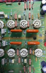
Update. I couldn't end day without checking more. Unsoldered R7 (R107 Left and this channel had lower volume). Resistance is infinite, bad resistor. By size I think it is 0,5 W. Will buy new and let's see, will channels have equal volume after. Seems Chris pointed right place 🙂
Attachments
In your photo in post #25, R19/R119 and R22/R122 look like they've gotten toasted some too. Really, any resistor that looks toasted should be replaced with something of higher power rating. Parts are cheap, but manufacturers too often don't give enough margin.
All good fortune,
Chris
All good fortune,
Chris
Hi Chris!
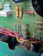
Yes theses R19/R119 and R22/122 seems to have changes in colour and are suspicious. Will replace. What to you think about R111, attached photo. Holes are burned colour and surface of resistor is like sandpaper. Same another channel R11.
I do not have components store in my town therefore will place online order. I am little confused about resistor power. On scheme is written that all resistors 0,5 W if not market otherwise. So the bad resistor is 0,5w. But I have some other value metal film resistors rated 1 W and it is a little smaller than this. See photo 2. Is it that nowadays resistors are smaller? Unfortunately colour code on resistor do not show rated power.
Is it better to replace theses with higher power rated resistors?
One question more. I have reed some time ago somewhere in forum that it is recommended to replace old amplifier electrolyte capacitors. This amp 26 years old, is it old? I can order also capacitors at once. What is your opinion?
Thanks,
Rait
Attachments
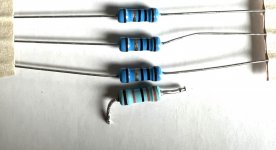
Some modern resistors are designed to run hotter, and can be rated at over 100C. Obviously, this is not good for surrounding parts or for the PCB itself. Looks good on paper, but not good 26 years later. Parts are cheap, and being conservative with parts ratings is just good insurance. Any parts showing signs of overheating should, by definition, be replaced by more conservatively rated parts. Obviously, nothing physically smaller than the originals - lesson learned by the manufacturer?
Resistors also have a voltage rating; within a brand and model, this usually increases with increasing power rating. Little metal-film resistors that fail open, but not obviously overheated, have probably died from exceeding their voltage rating. Again, the cure is a more conservatively rated part.
Your second image, of R111, looks like the resistor is not discolored, but its heat has discolored the PCB. If that's true, you might want to replace the solder in its solder joints. They've been through many cycles of heating-cooling-heating-cooling and their crystal structure is damaged. Easy and cheap insurance.
Electrolytic capacitors age rapidly at higher temperatures, even the good modern Japanese parts your pictures show. When you do replace them, use good modern Japanese parts, Nichicon or Panasonic or something of that quality, rated for 105C.
All good fortune,
Chris

Some modern resistors are designed to run hotter, and can be rated at over 100C. Obviously, this is not good for surrounding parts or for the PCB itself. Looks good on paper, but not good 26 years later. Parts are cheap, and being conservative with parts ratings is just good insurance. Any parts showing signs of overheating should, by definition, be replaced by more conservatively rated parts. Obviously, nothing physically smaller than the originals - lesson learned by the manufacturer?
Resistors also have a voltage rating; within a brand and model, this usually increases with increasing power rating. Little metal-film resistors that fail open, but not obviously overheated, have probably died from exceeding their voltage rating. Again, the cure is a more conservatively rated part.
Your second image, of R111, looks like the resistor is not discolored, but its heat has discolored the PCB. If that's true, you might want to replace the solder in its solder joints. They've been through many cycles of heating-cooling-heating-cooling and their crystal structure is damaged. Easy and cheap insurance.
Electrolytic capacitors age rapidly at higher temperatures, even the good modern Japanese parts your pictures show. When you do replace them, use good modern Japanese parts, Nichicon or Panasonic or something of that quality, rated for 105C.
All good fortune,
Chris
Thanks. There are Carbon and Metal film resistors. Tube amplifier has heat and higher voltages, what type to order?
I heard that Metal film is better if audio signal passed by and used theses when I build LM1875 base semiconductor amplifier many years ago. What is your opinion regarding Carbon or Metal Film resistors?
I figured it out myself, read DIYAUDIO forum. Metal film resistors have less noise and seems that my online supplier have also better options for Metal film resistors. Will order theses.
Hi.
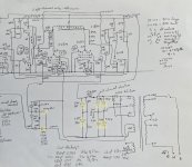
Thinking to replace capacitors with new ones in future. There are bigger area under factory installed 330uf 250v on PCB. New Nichicon 105C 330uf250v is same price as EPCOS/TDK 105C 470uf250v. Both are good producers. Will it be better to use higher capacitance? No harm from it? On diagram theses marked in yellow.
Thanks.
Attachments
I would not recommend larger power supply capacitors in any modern amplifier. If I'm repairing an amplifier for someone else, I won't use larger capacitors, even if they ask. I'm assuming that you have no audible hum, even near-field and with sensitive speakers, so there's no problem to be fixed.
OTOH, larger capacitors reduce the rectifiers' angle of conduction and increase peak currents, further stressing upstream parts (rectifiers, power transformer, etc.) and increasing the noise that they radiate into your chassis. All for no good purpose, IMO. Higher voltage ratings are fine, and might even increase working lifetime (some).
Good luck with your project, and have fun,
Chris
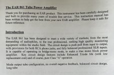
This is a really nice looking and nicely built unit that you have, and I wish you complete success with your efforts! Anyway, I'm quite astonished that it, in contrast to EAR 509 and EAR 549, also designed by TdP, apparently isn't a unity coupled design?
Best regards!
Best regards!
Kay, yes it is very good amplifier, I like it very much. It had some issues, but it is very quiet, good sounding and enough power. It works in class A on lower volumes, as I understand. Bought it 8 years ago second hand with defect, one channel power dropped time to time. Managed to fix it easy, it need to have over soldering on one of output tube sockets.
Now I have new issue with 20% lower gain on one channel but thanks to member Chris Hornbeck I now know what to fix and waiting new resistors delivery.
Designer Tim De Paravicini is no longer with us, but he have left very good amplifier to use to us. I have print of hand drawn diagram of it and thinking sometimes is it drawn by himself.
Tim didn't like to endlessly pump out the same circuits. As previously mentioned it is based on the 859 amplifier, but has no secondary feedback. The 859 amplifier "enhanced triode mode" was a response to the rise of the 300b SE.I'm quite astonished that it, in contrast to EAR 509 and EAR 549, also designed by TdP, apparently isn't a unity coupled design?
Last edited:
Tim didn't like to endlessly pump out the same circuits. As previously mentioned it is based on the 859 amplifier, but has no secondary feedback. The 859 amplifier "enhanced triode mode" was a response to the rise of the 300b SE.
Hbc, Do I understand you correctly, that my EAR 861 do not have feedback? I read from some review many years ago, that 861 works as class A up to half of power and then goes to AB class. I understand basics of tube amplifiers but 861 diagram to complicated for me to understand fully.
Thanks.
The hand drawn schematics in the postings above are barely to understand for anyone 🙄.
Best regards!
Best regards!
The 39ks correctly mentioned by Chris Hornbeck are feedback from the primary of the output transformer.
Yes, Chris mentioned theses. Understanding now, thanks for pointing out again. Do it means that it not in Class A? Class A is without feedback. Here is photo from manual where "Pure class A operation"The 39ks correctly mentioned by Chris Hornbeck are feedback from the primary of the output transformer.
Attachments
- Home
- Amplifiers
- Tubes / Valves
- Problem with old tube amp