Hi guys,
I have a problem with preamp Rеgа Сursа 3. The input selector does not function. Management is carried out by pic16c62b -> motor driver -> mechanical switch. Back in the day there was a service bulletin from Rega for additional grounding of this controller to the chassis, but my web search was unsuccessful.
However, from what I've read about such controllers, I understand that the chip inputs that are not in use should probably be grounded.
I welcome any advice.
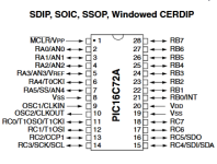
datasheet
Regards!
I have a problem with preamp Rеgа Сursа 3. The input selector does not function. Management is carried out by pic16c62b -> motor driver -> mechanical switch. Back in the day there was a service bulletin from Rega for additional grounding of this controller to the chassis, but my web search was unsuccessful.
However, from what I've read about such controllers, I understand that the chip inputs that are not in use should probably be grounded.
I welcome any advice.
datasheet
Regards!
Attachments
Your best bet is to either find a schematic or to look at the circuit board for unconnected pads on the PIC.
Tom
Tom
I didn't find a schematic, but I will check on the circuit board.
Which pins, if free, do you suggest I ground?
Which pins, if free, do you suggest I ground?
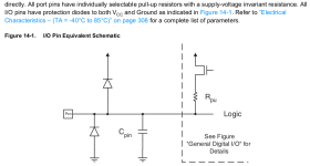
Hi. It's bad idea to ground unused processors pins. Pic controller has one difference from just logic ic - logic ic may have unused inputs, whose better not to be left floating. But processor's unused pins will have no action if their function is not defined in code while programming. Also same pin can be used as input or output, function defined when writing code. Another case is when same cpu is used in different models of similar devices, and some pins are left unconnected in some model's, but firmware is the same. What will happen if you ground unused pin, thinking that it's input, but in code it's definition is output? Cpu will be damaged, if for any reason will try to output logic "1". So if you are not 100 percent sure which pins can be safely grounded, use resistor 10k in series to gnd.
But in your case if input selector is not working, there are several possible causes. Cpu itself is bad, firmware become corrupt, and you need to reflash it, or clone from similar cpu, if that's possible, or conditions to work not meet, or cpu surrounding parts are bad, like voltage supervisor ic. Maybe processor is thinking unit is in standby, or that supply voltage is too low, or some other, defined in code. Sometimes it's clear by looking at schematic. If schematic not available, you have to draw it by yourself, or use another processor and make your own module , to work same way and perform same function.
But in your case if input selector is not working, there are several possible causes. Cpu itself is bad, firmware become corrupt, and you need to reflash it, or clone from similar cpu, if that's possible, or conditions to work not meet, or cpu surrounding parts are bad, like voltage supervisor ic. Maybe processor is thinking unit is in standby, or that supply voltage is too low, or some other, defined in code. Sometimes it's clear by looking at schematic. If schematic not available, you have to draw it by yourself, or use another processor and make your own module , to work same way and perform same function.
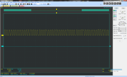
you need to establish if the cpu is running. inspect the clock. no clock no cpu. Check if MCLR is high. Code does not just disappear unless it is set to program mode.
Sometimes firmware in old units can become bad. EPROM memory is not same as oldest memory chips, where a jumpers were burned by programming. Eeprom stores charge and that charge decreases with time, however not few years are needed for corruption. On this forum there are several posts about corrupt firmware on old cd players as example.
Sometime you can just reload the firmware and the PIC/ATmega/ESP32 will run good again.
I play with all 3 (LED's and protection circuits).
I had an old Nvidia card act "squirrely" , reflashed the video bios with a added verbose command (shows on boot)
even changed the fan speed. Worked perfect afterwards (old GT560).
OS
I play with all 3 (LED's and protection circuits).
I had an old Nvidia card act "squirrely" , reflashed the video bios with a added verbose command (shows on boot)
even changed the fan speed. Worked perfect afterwards (old GT560).
OS

Hi guys,
The only free pins are 25 and 26 which have 4.95V. I connected them to ground with 10k resistors, but there was no improvement.
There is 5V on MCLR pin1, clock is Ok.
i don't have the firmware and i have no way to flash it even if i had it.
Is there anything else I can do?
The only free pins are 25 and 26 which have 4.95V. I connected them to ground with 10k resistors, but there was no improvement.
There is 5V on MCLR pin1, clock is Ok.
i don't have the firmware and i have no way to flash it even if i had it.
Is there anything else I can do?
You can check voltages on cpu pins, when you press button, if voltage on some input changes, and check how motor is connected. Maybe motor itself or it's driver is not functioning, not cpu.
Where is going pin 14? To driver ic or transistors maybe ? Can you somehow disconnect this pin or track, maybe desolder resistor or transistor ,jumper, whatever, to check where those 5v appears on - from processor itself, or from motor driver?
Pin 14 goes to driver ic LB1642.
I cut the track and now the voltage is gone, neither on pin 14 nor on the driver IC - pin 7 ??? wtf
I cut the track and now the voltage is gone, neither on pin 14 nor on the driver IC - pin 7 ??? wtf
Last edited:
Pin 14 may be pulled up by driver IC and turning the motor needs pulling down. Is the oscilloscope from the clock on the PIC or some other pin.
NO, it is set in software. Don't try and change the PIC I/O by pulling it to anything.I didn't find a schematic, but I will check on the circuit board.
Which pins, if free, do you suggest I ground?
I'm not sure if I understood correctly, but the measurement is between pin 14 and chassis ground.Is the oscilloscope from the clock on the PIC or some other pin.
- Home
- Amplifiers
- Solid State
- Problem with input selector