I just looked at a photo of that pre-amp. I cannot imagine why they have a motorised pot driver by a PIC with a pulse generator into the PIC to position the motorised pot (lame). Almost as if someone had some free time on his hands. There is no sonic advantage in that. The schematic I found does not even show the PIC, it seems to be situated on the front panel board.
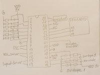
This is going to be difficult but what you could do is the figure out which I/O on the PIC is used for what. There should be, volume up/down select then a pulse train as you turn the volume. The volume control to the motorised volume should have two I/O one turning it up and one turning it doewn. The input selector I would assume is a push button that just sends a pulse for every push and you should see some I/O change with every push. There are a lot of LED displays around the volume control which will be entirely software and each LED would be driven by an I/O on the PIC. If the guy who wrote the software placed all similar functions on the same port, but knowing software he probably did not and just randomly selected I/O from top to bottom..
Yes, they are on front panel board.
The screenshot of the scope is from input selector control.
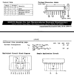
There are two LB1642 motor drivers.
The screenshot of the scope is from input selector control.
There are two LB1642 motor drivers.
Once you are familiar what I/O activates what you can start looking at the driver circuitry to see if things actually happen as it is supposed to.
The motor control IC works something like this schematic.

WHEN SWITCH ONE CLOSES THE MOTOR ROTATES IN ONE DIRECTION AND IF sWITCH2 CLOSED IT RUNS IN THE OTHER DIRECT WHEN BOT GROUNDED THE MOTOR STOPS
WHEN SWITCH ONE CLOSES THE MOTOR ROTATES IN ONE DIRECTION AND IF sWITCH2 CLOSED IT RUNS IN THE OTHER DIRECT WHEN BOT GROUNDED THE MOTOR STOPS
I cannot image them using a linear motor for input selection, either stepper motor or relays. Those would probably each be driven from an I/O or maybe through some BCD decoder driver. Same with the tons of lLEDs around the volume control. I would image this would also be through a binary to decimal decoder, else too many I/O would be required driving each selectively.
There are two more chips on the board: 74HC595D and LM3914N-1. I think they are responsible for the LEDs
So now when you identified each function on the PIC we may start to trouble shoot. One thing that I am not sure of is whether they keep power on the front board even when you turn it off. If the designer was smart he would call a reset at power on, but maybe he wanted to be clever and remember your last settings stored in RAM, then you would have to try just resetting the PIC by pulling MCLR low. (it is pulled high by 10K so just short it to ground, maybe this alone resets and solves the problem. Now a smart SW engineer would have used the watchdog to bail out of a problem situation but if a condition was written into EEProm that may still cause a hang, but at least you generated a master reset on the PIC which may reload some default values from EEProm when the program is reinitialized and executes from the beginning. Am I going to fast or can you keep up?
Last edited:
74HC595D is a shift register and probably to select one of many LEDs. TheLM3914N-1 is a ten LED bar-graph driver maybe similar operated from an analogue input source?? So there is no interface from this with the PIC it simply reads the analog position of the volume control and turns on the LEDs. This is unusual. But who knows what the designer had in mind.
Last edited:
Back in action.
First let me say that I made a mistake. The wrong signal comes from pin 13 of the PIC. When this track to the driver is cut, the signal remains. Therefore, the error is in the PIC.
Resetting via MCLR does not solve the problem (no power on shutdown, amp no standby power).
First let me say that I made a mistake. The wrong signal comes from pin 13 of the PIC. When this track to the driver is cut, the signal remains. Therefore, the error is in the PIC.
Resetting via MCLR does not solve the problem (no power on shutdown, amp no standby power).
Try to measure this pin with multimeter in diode mode, to +5v power supply pin. It must show only as diode in one direction, and not have ohmic or kiloohms resistance in normal ohms mode. If you find low resistance to plus supply, it's clear that cpu is physically fault. Only one idea is then to copy firmware from it to new blank cpu, but that's not allways possible.

In one direction there is a drop of 0.747V, in the opposite direction 1.7 to 1.8V (as if charging a capacitor). In ohmic resistance 3.9k, in the opposite direction 4.6k
__________edit
but the measurement is the same on pins 11 and 12 which control volume, and this works correctly.
__________edit
but the measurement is the same on pins 11 and 12 which control volume, and this works correctly.
Last edited:
Ok, so it looks like output not shorted, maybe still firmware fault.
Maybe there's some kind of feedback, position of switch, which tells to processor, that end position is reached and motor should not rotate at this direction any more. Clearly determine function of all cpu pins like input, output.
Maybe there's some kind of feedback, position of switch, which tells to processor, that end position is reached and motor should not rotate at this direction any more. Clearly determine function of all cpu pins like input, output.
Last edited:
I'll try to clear this up.
Meanwhile, I have read that such problems can be caused by static electricity. Is there anything I can do about this?
Meanwhile, I have read that such problems can be caused by static electricity. Is there anything I can do about this?
Static electricity can cause some damage on sensitive inputs, if they are floating, and no esd protection diodes present. But novadays i see those diodes on all pins on every ic. So probably add protection is only one solution.
- Home
- Amplifiers
- Solid State
- Problem with input selector