Thanks Elvee.
That I can understand.
looking at the 3rd sim.
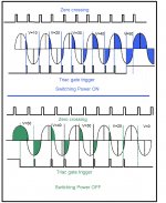
The switch on at zero crossing shows low current for the first 90degrees or so.
Then the sudden increase in current after that 90degrees, when saturation of the core has been reached. The peak start up current occurs at ~120degrees into the voltage phase and subsides to low at just over 180degrees. From there on the transformer behaves as a normal fully energised device drawing just quiescent current.
This sim shows that the start up transient is all over in ~ half a wave length + 10° say ~190°.
Have I interpreted the sim correctly?
Is this what we see in real life? Does experimental data show the same behaviour?
That I can understand.
looking at the 3rd sim.
The switch on at zero crossing shows low current for the first 90degrees or so.
Then the sudden increase in current after that 90degrees, when saturation of the core has been reached. The peak start up current occurs at ~120degrees into the voltage phase and subsides to low at just over 180degrees. From there on the transformer behaves as a normal fully energised device drawing just quiescent current.
This sim shows that the start up transient is all over in ~ half a wave length + 10° say ~190°.
Have I interpreted the sim correctly?
Is this what we see in real life? Does experimental data show the same behaviour?
Last edited:
post79.
have the 10A/div & 50A/div labels been swapped between 3A & 3B and again in 4A & 4B?
If the labels are swapped the narrative seems to fit.
This is from post70 link
The peak transient start up current when the transformer is switched on is limited by the primary resistance. They have omitted the effect of source resistance, which at these values will be significant.
It appears that the science of the zero crossing switching and the Vpk switching has eluded me. It also appears that the core saturation occurring some time after switch on, was beyond me.
But it does appear that the start up current is dominated by the primary resistance (+ Rs).
From this, I return to my original solution. Just add a big resistor value into the Primary circuit.
have the 10A/div & 50A/div labels been swapped between 3A & 3B and again in 4A & 4B?
If the labels are swapped the narrative seems to fit.
This is from post70 link
I had to edit the calculation slightly due to the use of 2 lines in the original text.A 150 VA transformer has a 120 volt primary DC resistance of
approximately 1.5 ohm, and a 500 VA transformer, a 120 volt primary
resistance of approximately 0.3 ohm. One might think a 5 amp zerocrossover
SSR would be more than sufficient to switch the current of
the 150 VA transformer. However, during core saturation, primary-winding
inrush is 80 amps:
I = E/R = 120/1.5 = 80 amps.
The peak transient start up current when the transformer is switched on is limited by the primary resistance. They have omitted the effect of source resistance, which at these values will be significant.
It appears that the science of the zero crossing switching and the Vpk switching has eluded me. It also appears that the core saturation occurring some time after switch on, was beyond me.
But it does appear that the start up current is dominated by the primary resistance (+ Rs).
From this, I return to my original solution. Just add a big resistor value into the Primary circuit.
Last edited:
Wikipedia seems to have said much of what we have been debating . Even the graph looks familiar ( 43 ) . Perhaps our contributor ? I note auto-transformers seem to have the lowest inrush , any thoughts ?
https://en.wikipedia.org/wiki/Inrush_current
https://en.wikipedia.org/wiki/Inrush_current
Last edited:
Andrew . I was told many years ago that the ideal Niam Audio set was perhaps unworkable with how they designed transformers . The NAP 250 would often take out 13 A mains fuses as I have already said . The Naim preference was to use over-sized cable back to the incoming supply . The critic said it was only the resistance and inductance of the domestic mains electricity that allowed such a transformer to work . Certainly where I worked NAP 250 would dim the lights when switching on . I seem to remember 6 V of drop is allowed on our mains at full loading ( forgive me if wrong ) . 32 A at 6 V = < 0.2 R ( normal ring ) .
I must say however I know of a strange exception . I wired my friends house with what must be the shortest ring main in the world . His meter cupboard is behind the equipment by pure chance ( outside of the house via 2 layers of brick to his alcove ) . If it has 3 metres of cable total I would be surprised ( 32 A with 8 sockets all in a row , Crabtree with no switches ) . The NAP 250 has been impeccable and I never saw the lights surge . Interesting . Think I can see why .
When I switch on a kettle the lights dim in the house . That is the overall effect and not the ring main as the lights do not use the ring main . They only return to normal when the kettle switches off ( about 2.5 V ) . The Naim situation as can be imagined as down then up . From memory about a second . The dip seems lower than the kettle ( circa 10 V ? )
Last edited:
A close rated fuse does the job of protecting the house far better than using a 20A/25A/30A breaker.
Close rated fusing can only be used for a transformer if some means (current limiter) is adopted or designed into the starting up sequence.
Close rated fusing can only be used for a transformer if some means (current limiter) is adopted or designed into the starting up sequence.
Can anyone show corroborating experimental data for transformer start up currents for real transformer/s used in Power Amplifiers?
maximum possible inrush current happens when the primary of the transformer is turned on at the peak of the wave cycle, and it is Vpk/Rdcr, where Vpk is the peak of the ac input voltage and Rdcr is the dc resistance of the transformer primary, i can not imagine getting higher currents than this....
it is this current that needs to be tamed by adding resistance in series to lower this current.....can not be simpler than this....
Have you been listening to anyone? As I said in post 64, "too much simplification leads to errors in understanding". Your conclusion couldn't be any more incorrect.
First people try to educate you, then you reply with a sarcastic comment- that's priceless.ohm's law does not apply here apparently....
Attached is a TYPICAL capture of transformer inrush. I apologize that I am using a three phase system at 4160V into a 10 MVA transformer, so it is a tad out of scope from the tiny little toroid transformer. But really, inrush is as described in post 64, it's NOT as simple as DCR-limiting, and you can clearly see the decaying exponential of DC as a result of the initial offset of flux. All questions about zero crossing, phase angle, etc are not addressed by this pdf, of course. But when something as well known as the inrush phenomenon (which has been thoroughly studied in the power engineering field) gets rewritten by the audio forum, it gets wearying. Tony, you may use your ohm's law to show how a real world capture follows your calculation - after all, it "cannot be simpler than this".
Attachments
Back to some of the science that was eluding me.
Much has been posted that the start up current saturates the core. Further posting indicate that the core flux is roughly doubled in that start up phase.
If the primary turns were doubled, would that avoid or reduce the saturation that has been mentioned?
If a 115/230Vac universal transformer were wired up as a 230Vac and plugged into a 115Vac supply, would the saturation problem go away and there would be no peaking of the start up current?
Just order up a universal transformer with a doubled VA rating !!!!
Is the solution for the 115Vac countries that simple?
Last edited:
We can also try reversing HT transformers I guess ( 350 V ) . I was told under-saturated transformers might buzz . I presume that is what we are talking about here ?
Garrard turntable motors often tolerated being connected to 240V on the 120 V connection . This would be tolerated for some hours . They were indescribably hot when disconnected ( they run hot if correctly connected ) . The Garrard 270 V safe working seems to be an under estimate ! Well done Garrard .
If a Garrard motor is held the current hardly increases . Not a great proof of anything . Interesting . The typical is about 16 W or 24 VA . Perhaps the stall current increase is the actual output power to a good approximation ? The motor is a shaded pole induction type . Much my preferred type as it has no notches as it rotates . The difference between synchronous , stepper and DC is subtle . Induction a better choice .
I think you have now got what we are saying, but just to clarify that the instantaneous start up current (i.e the current at time t=0+, just after the switch closes) is always zero because no inductor can change its current instantaneously. Even an air-core inductor can't change instantaneously.AndrewT said:The "myth" claims that for the first case (zero crossing) the instantaneous start up current is at worst case maximum and in the second case (at Vpeak) the instantaneous start up current is zero because transformer behaves as an inductor.
I'm pleased you have now got it. Even 'simple' things like inductors can have surprises and somewhat counter-intuitive behaviour. As I have said before, engineering intuition is a bit like conscience: if not properly constrained it can lead us astray.AndrewT said:It appears that the science of the zero crossing switching and the Vpk switching has eluded me. It also appears that the core saturation occurring some time after switch on, was beyond me.
But it does appear that the start up current is dominated by the primary resistance (+ Rs).
I believe so, yes. One slight caveat: some cheap transformers are on the edge of saturation when unloaded and at their nominal input voltage. They rely on the primary resistance dropping a little voltage when the secondary is loaded, so getting them under the saturation limit in normal use. Such a transformer might dip into saturation if unloaded because the doubled input current could just push it over the edge.AndrewT said:If a 115/230Vac universal transformer were wired up as a 230Vac and plugged into a 115Vac supply, would the saturation problem go away and there would be no peaking of the start up current?
This behaviour probably means that the motor, like many small motors, is quite inefficient. If you think of it as a mechanical analogue of a transformer, then it is one with poor coupling between primary and secondary so the leakage inductance is not much smaller than the primary inductance. You might see a change in current phase when the motor stalls, to a more inductive state because there is no mechanical work being done so the only resistive element is from the windings.nigel pearson said:If a Garrard motor is held the current hardly increases . Not a great proof of anything . Interesting . The typical is about 16 W or 24 VA . Perhaps the stall current increase is the actual output power to a good approximation ?
If you look more closely, you will see the remnants of a peak at 360°.The peak start up current occurs at ~120degrees into the voltage phase and subsides to low at just over 180degrees. From there on the transformer behaves as a normal fully energised device drawing just quiescent current.
This is the situation for a cheapo, relatively small transformer.
Larger and better transformer have better (larger) L/R ratios, meaning the transient will take more time to die away.
YesHave I interpreted the sim correctly?
The inherent self inductance of the winding (the one not affected by the iron core) does also play a role, but it is highly dependent on the transformer size (big transformers have lower resistances) and its construction.But it does appear that the start up current is dominated by the primary resistance (+ Rs).
Small for a toroid because there is little crowding effect from the turns spread around the core, high for a conventional EI where the form factor of the winding is near optimum for inductance.
And it is maximized for the non-preferred construction mode where the primary is the outermost winding.
Yes, but it is highly dependent on the particular transformer, its size, its construction (toroidal, split bobbin, double C, superposed, etc), the design tradeoffs, etcIs this what we see in real life? Does experimental data show the same behaviour?
Yes, for practical purposes, using 180% the number of turns normally required for a given core area will eliminate completely any power-on surge (the inductive one at least)If the primary turns were doubled, would that avoid or reduce the saturation that has been mentioned?
Yes and no: it is inefficient, and the regulation will also be halved.Just order up a universal transformer with a doubled VA rating !!!!
Is the solution for the 115Vac countries that simple?
I don't think so. The opposite in fact.We can also try reversing HT transformers I guess ( 350 V ) . I was told under-saturated transformers might buzz
The cos phi does change, and besides, shaded pole motors are pretty inefficient anyway.If a Garrard motor is held the current hardly increases . Not a great proof of anything . Interesting . The typical is about 16 W or 24 VA . Perhaps the stall current increase is the actual output power to a good approximation ? The motor is a shaded pole induction type .
Last edited:
I will try the 350 V is as the sample I have is bad . Will be interesting .
I think a bit of the induction motor magic is that they work very well for this size and this application . Getting them now is difficult . I saw some 6 pole from ventilators I would like to try .
Anyone like to say why auto-transformers have less inrush ? I suspect the close association between input and output helps ? The magnetic circuit is not exactly like the isolation type . I have known a 4000 VA type start on a 2 A fuse ( it was hunch so I tried it ) . I doubt a 500VA toroid would .
This GE paper is interesting
http://store.gedigitalenergy.com/faq/Documents/T35/GER-3989A.pdf
Last edited:
Conventional E-I (etc.) transformers have higher resistance and probably smoother transition to saturation. Both effects reduce the size of the initial peak. The higher resistance also makes the transient DC decay more quickly. Taken together this puts less strain on the fuse, which will take a lot more than 2A before it blows anyway.nigel pearson said:I have known a 4000 VA type start on a 2 A fuse ( it was hunch so I tried it ) . I doubt a 500VA toroid would .
Anyone like to say why auto-transformers have less inrush ?
Probably because for a given power, there is more window area available compared to a normal transformer, since primary and secondary are one so to say (partly at least).
This eases the constraints and allows more copper.
Years ago and very distant in my memory a book said that were it not for self inductance the transformer would not be viable . Back EMF was mentioned as proof . Is this correct ?
I tried to make a resonant transformer from a standard 25 V toroid with one winding as the resonator . It worked although everything got very hot including the capacitors ( non polar electrolytic ) . I am told these transformers have different ways of working and often will not allow a motor to start . The related device can be made to amplify about to the standard of a SE valve amp or better ( about 1 % distortion up to 200 kW ) . I did wonder if a slight bit of resonance and a timer on a spare winding could do something ? I did get about a halving of distortion on my attempt ( down to 2 % as a guess ) . It did regulate voltage nicely . Alas I kept no notes due to the heat being a problem . Some say CVT's will complete a cycle or two in a brown out , no idea if true . Mine didn't . If I tried again I suspect a high voltage transformer would have worked better ? My transformer designer says the art of these is various shunts and air gaps . Oneac seem to be a brand leader .
http://www.pqsi.com/pdfs/IEC CVT.pdf
I think it is fair to say that self-inductance is important, because that limits normal primary current. Mutual inductance then couples to the secondary. 'Back EMF' is just another name for normal inductor action. Inductors don't like changing their current.nigel pearson said:Years ago and very distant in my memory a book said that were it not for self inductance the transformer would not be viable . Back EMF was mentioned as proof . Is this correct ?
This is it an update report of the project. Attached it is a timing diagram of the final timing programmed in the micro for the switch ON/OFF sequence. The final timing was tested in both EI and a toroidal transformer without any current spiked. Ran both 500 times flawless without any problem. Also I used it to turn on a light bulb and ran as dimmer. Everything ran smoothed. Now I am still working in the printed circuit board. The final module it is going to be an stand alone chassis to allow it to be use externally without any internal modification.
Attachments
I think it is fair to say that self-inductance is important, because that limits normal primary current. Mutual inductance then couples to the secondary. 'Back EMF' is just another name for normal inductor action. Inductors don't like changing their current.
That's my auto-transformer proof I think ? The mutual coupling is very tight ?
Would anyone like to speculate about auto-transformer energy decay ?
An auto-transformer has perfect coupling for that part of the winding which is common to primary and secondary circuits. This may be only half the winding, though. Unlikely to directly affect the inrush current.
- Status
- Not open for further replies.
- Home
- Amplifiers
- Power Supplies
- Preventing the inrush current saturation in a toroidal/EI transformer