Naim especially played games with transformers . When Holden and Fischer ( spellings ) went bust Naim were quick to get their intellectual property removed ( drawings ) . On reading books on transformer design the Naim ones would suggest defective thinking to the conventional engineer . This clever trick does seem to give an extra strength to the bass quality . It is also a cost free thing . The fine judgement of how to do it is an art . Please anyone at Naim do not take this as criticism , quite the opposite . As said I would have gone further using a series resistor and relay .
My 3.3 KVA is designed properly as an industrial device . No surge worth noting .
My 3.3 KVA is designed properly as an industrial device . No surge worth noting .
I'm not quite sure what it is that you have never heard before, but the initial DC current in a mains-fed transformer is well known. It happens with all transformers but is usually only noticeable with a toroidal, due to the low DC resistance of the primary.krokkenoster said:This is something that I never heard before! Is the problem not due to very large electrolytics in the secondary circuit.?
The explanation involves looking at sine waves and the definition of inductance; ideally using calculus.
Every profession has idiots. It is generally unwise to extrapolate from a sample of one.
I don't understand- why don't you just use a current inrush limiter? They work great- installations I've done 30 years ago are still running fine with no damage to the power switch. What am I missing here??
Exactly. Simple inrush limiter solutions are well known, so why complicate it all with fancy semiconductor switches and their drive circuitry? Just one more thing to go wrong one day.What am I missing here??
Hi,
Thank you everybody for the information. Right now I am out of town so my project it is on hold. I ran my prototype in a loop 500 times ramping up/down flauwless. No problems. I need to do the test with a toroidal and if it is ran OKAY I would said that the problem it is fix. I am going to take some pictures of the scope showing the secondary AC wave form of the output. There it is not spikes and it is cleaned.
Thank you everybody for the information. Right now I am out of town so my project it is on hold. I ran my prototype in a loop 500 times ramping up/down flauwless. No problems. I need to do the test with a toroidal and if it is ran OKAY I would said that the problem it is fix. I am going to take some pictures of the scope showing the secondary AC wave form of the output. There it is not spikes and it is cleaned.
Well this is a challenge for me. I would like to fix the problem permantly and I think I am in the right track. I also used current inrush limiter in all of my repaired but I still think this is a better solution slowly ramping the volatge from zero to max voltage without any spikes or noise. Nobody can stop you from using the inrush current limiter.
I'm not quite sure what it is that you have never heard before, but the initial DC current in a mains-fed transformer is well known. It happens with all transformers but is usually only noticeable with a toroidal, due to the low DC resistance of the primary.
The explanation involves looking at sine waves and the definition of inductance; ideally using calculus.
Every profession has idiots. It is generally unwise to extrapolate from a sample of one.
I think for once maths of age 6 will do . I have just measured a 500 VA toroid and 250 VA E-I transformer . < 3 ohms 500 VA and < 4 ohms 250 VA . The latter surprised me . If 240V that suggests circa 20 kW for the 500 VA initially ( just an industrial one ) . The inductance quickly is added in series to that as it charges ( other factors also ) . It one wants to see this in action add a 100 W filament light bulb in series . It is worth pointing out that light bulbs are interesting in themselves ( PTC ) . Get your meter out and do the sums . Many service engineers use them to protect equipment under investigation .
This brings me to a rather alarming point . Most small equipment has for example a 100 VA toroid running on a 1AT fuse ( 230V ) . It works fine and I have never seen a problem . A 1 amp fuse will pass 2 amps for at least an hour often . A slight defect could cause a fire . Rotel fit a thermal fuse in their transformers , many do not . Again the relay is highly desirable as a < 400 mA fuse could be used . A preferable solution which I suspect no Audiophile company would look at would be to just to use a series resistor if a small load . This is the antithesis of Naim . I will do some measurements one day to see where this goes .
I ran a 10 A kettle on a 6.3AT ( HRC ) fuse for days . It refused to pop . I suspect it would have lasted years . That is the reverse situation , the kettle is a pure resistor more or less .
The unloaded 500VA probably uses < 12VA when magnetically charged .
About knowledge . At the pub I drink with a friend who builds magnetometers , hi fi is his passion . His work is highly secret and can not share it even with me . We were joined by Richard who I have known for years yet have never met . He is a local TV repair man . Richard apologized for his lack of knowledge . I insisted he was the most knowledgeable of all of us . John might be a Surgeon and me a simple doctor . Richard is a Veterinarian ( Vet ) and that means his knowledge is broader than ours .
Last edited:
As what charges? The transformer resistance does not directly translate into starting current, as the inductance is still there and you have to take account of what is connected to the secondary too.nigel pearson said:The inductance quickly is added in series to that as it charges ( other factors also ) .
Nigel,
you are explaining it well.
It is not complicated.
I will extend your argument just a little further.
The 500VA transformer has a 3r0 primary resistance. If you add a T2A fuse in series and try switching on the T rated fuse will blow.
What resistor needs to be added in series with the primary such that the T2A fuse does not blow on repeated start up over many years.
I'll guess at 50r. Try it. It will almost certainly work.
Why?
Because the T2A fuse can pass many amps for a few milliseconds and many tens of amps for a few microseconds. The 240vac mains could have a peak instaneous voltage at switch on of 340Vpk. The 3r0 + 50r would allow a peak instantaneous current of 6.4Apk for the first microsecond. this instantaneous current drops very rapidly down towards the quiescent AC current of may be 50mAac. The fuse does noit blow because that very short very high current pulse that rapidly decyed did not heat the metal of the fuse sufficiently to melt.
You could try a T1.6A fuse and see how long it works.
Similarly for the 250VA transformer with the 4r0 primary. try a 60r resistor. It will probably start the transformer repeatedly when a T1A fuse is fitted. Again it may start repeatedly with a T800mA fuse. It is worth experimenting.
DF you make a valid point that is technically correct. But in practice the magnetic flux and the core have almost zero effect at the instant of start up.
The primary resistance and the other resistances in the primary circuit dominate the instantaneous start up current. The inductance determines how rapidly the current decays to the quiescent value. By then the heat capacity of that bit of melt-able wire has ensured that the fuse does not blow.
Last edited:
Andrew, are you making the same mistake as Nigel? Even if the transformer secondary is shorted you still have to reflect the secondary winding resistance back to the primary, which could easily double the effective primary resistance. Then in real life the secondary is not shorted, it probably has a bridge and reservoir cap which add more resistance even when the cap is uncharged.
Simply using the measured primary resistance and assuming this will give you the initial starting transient current is wrong. It will overestimate by quite a lot, perhaps a factor of 2 or 3.
Simply using the measured primary resistance and assuming this will give you the initial starting transient current is wrong. It will overestimate by quite a lot, perhaps a factor of 2 or 3.
you should add up all the primary circuit resistances as I explained. Then you will find that a close rated fuse can be made to reliably survive repeated start ups.
When you add all the primary circuit resistances together you will find that a doubling or even a tripling of the primary resistance has little effect.
However if you were to attempt start up without any added primary circuit resistances, then clearly the close rated fuse will rupture. It does not need the capacitor bank to be there or not to save that close rated fuse.
Why?AndrewT said:But in practice the magnetic flux and the core have almost zero effect at the instant of start up.
Thanks Andrew .
I remember when I went to NASA they were very proud of the fact that pre Einstein maths was good enough to travel in our solar system . My point was that the evidence of my ohm meter would say how does this have the slightest chance of working ? Work it does .
I have always been a bit " Phlogiston " and admit it . Even though I did the maths I only resort to it when rules of thumbs don't work ( often if I am honest ) .
DF leads me to a tangent . It was said by someone that a PP valve transformer does not have hysteresis effects when at zero signal . I could not accept that . However if the situation is complex it might require more thought . I would say deliberately having a slight imbalance of valves in PP might be advantageous and I do not mean second harmonic distortion . 19 kHz pilot tone might even do good ! Like AC bias in tape circuits . I suspect DC bias of SE is no bad thing . Having measured class D amps I am astonished that they sound in the least bit good . The one I measured years ago was dreadful . I have to say it sounded better than TDA2030 etc . It was old school class D ( before Hypex ) .
At Christmas last year I was diagnosed with Parkinson's . It seemed to change me . I was no longer able to calculate things . Before that I spent hours doing it . I had also almost completely lost confidence in doing electronics . Friends were angry with me and said I was taking the P with the questions I asked . I genuinely did not know the answers . I have practically had to relearn . This forum has helped greatly . The one thing I have been able to do recently is maths . However I have let go and don't want to do it as I used to . DF told me something was just polynomials the other day . I know it is , I needed telling . I said I almost cried . I lied as I did a bit . Just yesterday someone said to me a friend with Parkinson's had a similar experience . The sad bit of this story is before I regained my mental strength people said I was a much nicer person .
Hey ho .
why?
initial condition of inductors are "open circuit" as opposed to capacitors which are "short circuit" at turn on(provided that cap was not previously charged)....therefore the dc resistance of the transformer primary winding limits current at turn-on...
turn on current depends opun which part of the ac cyle the turn on occurred, it is low at zero crossing and maximum at the peak of the cylcle...
If the initial condition of an inductor is open circuit, which is what I believe, then the consequence is that the initial current is zero. The current then builds up according to the inductance (which for a shorted transformer is the leakage inductance) and may then, perhaps, be limited by the voltage drop across the resistance.Tony said:initial condition of inductors are "open circuit" as opposed to capacitors which are "short circuit" at turn on(provided that cap was not previously charged)....therefore the dc resistance of the transformer primary winding limits current at turn-on...
The resistance also plays a different role. Together with the inductance it gives an L/R time constant which determines how quickly the initial DC current subsides. Yes, attach an inductor such as a transformer to a pure AC supply and you get an initial DC current (except if you connect it at the voltage peak).
Essentially what DF96 is saying is that y'all are making simple calculations on a symmetrical consideration only. The inductance contributes to the asymmetrical current, which is significant and the fuse will certainly see.
yes, the dc resistance is what contributes to large turn on currents, the inductance part contributes 0 current, the inductance is what brings the current down depending on time constant formed by the dcr and inductance of the primary winding....
which brings on the fact that a simple power resistor several times larger than dcr is all it takes to bring down the startup current to more manageable levels....
a simple delay timer relay shorting this resistor out completes the circuit....just like AndrewT proposed in post #11...
which brings on the fact that a simple power resistor several times larger than dcr is all it takes to bring down the startup current to more manageable levels....
a simple delay timer relay shorting this resistor out completes the circuit....just like AndrewT proposed in post #11...
The advantage of the relay-resistor solution is a more ideal transformer can be used . Or more ideal safety . Options are always interesting . It is nice to be able to have a dramatic outcome from science . I certainly would have grasped this aged 6 ( less so now ? doubtless ) . Not saying it is simple , just simple to manipulate . That is rare in engineering .
Walter Jung came out with an article published at the Audio Magazine in the 80's describing such schemes....
Hi,
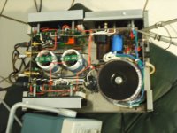
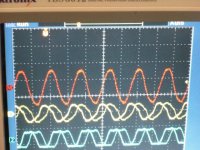
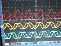
I am back home immediately started working on my project. Ran the same test I did to the EI transformer using a Dynaco 120 with a toroidal transformer. Ran it by ramp the voltage up/down repeatability for 500 times with the same results as the EI transformer. No blown fuses or spikes. Attached are some pictures showing the waves going up/down the peak. I have to scope them differentially due to probes are ground in the scope. The red line it is the differential. You can see that waves are clean with no spikes what so ever. Now I am working in the printed circuit board to finish the project. Well I need to do one more test and it is test it in an equipment using tubes to see how the filaments look like when the voltage it is slowly ramp up.
I am back home immediately started working on my project. Ran the same test I did to the EI transformer using a Dynaco 120 with a toroidal transformer. Ran it by ramp the voltage up/down repeatability for 500 times with the same results as the EI transformer. No blown fuses or spikes. Attached are some pictures showing the waves going up/down the peak. I have to scope them differentially due to probes are ground in the scope. The red line it is the differential. You can see that waves are clean with no spikes what so ever. Now I am working in the printed circuit board to finish the project. Well I need to do one more test and it is test it in an equipment using tubes to see how the filaments look like when the voltage it is slowly ramp up.
Attachments


- Status
- Not open for further replies.
- Home
- Amplifiers
- Power Supplies
- Preventing the inrush current saturation in a toroidal/EI transformer