It is still fun to see a new ACA board variation. I like the idea of a capacitance multiplier and the CRC section before the CapMX is good in order to reduce the dropout voltage.
As I have been working with other LT4320 and CapMx designs recently, I have some experience that I would like to share: F6 Amplifier. The PCB layout could be modified to add some simple connectors to allow a large screw terminal cap to be added in parallel with the 1000 uF cap on the output of the CapMx section.
Even though the amp I refer to is an F6, the bias current is similar, so some of the other measured parameters should be close to an ACA built with these new boards. I would suggest a 300VA power transformer with either 22V or 24V secondaries. In this case the 200 Ohm resistor to the left of the LSK170 could be increased to 499 or 1k Ohms to reduce the power dissipation in that expensive little JFet. A pair of IRFP140 Mosfets also will do a fine job with higher power supply voltage.
A question regarding the transformer requirement for this new ACA build. I have a Toroidal rated 0-22v + 0-22v @6.8 dual secondary which comes to around 300VA. Does this board needs single secondary AC transformer? If so can I use each of these 22v secondary for each amplifier board which makes it like 3.4A per secondary? Or am I missing something with the ACA being single polarity psu requirements rather than bipolar.
Thanks
Two transformer secondaries are what you need.
Connect each secondary to an ACA-PCB (PSU).
What I dont know (since I do not have experience): is the ACA able to handle a 28-29 VDC supply (that is what I expect your transformer and the CAPMx will output).
Rudi
Hi Rudi,
What should be the transformer ratings
Regards
cL00sed: I did only have access to an INDEL 2 x 19VAC / 160VA transformer; this is what I use.
TungsteAudio - as he has written - uses a 2 x 22VAC transformer.
The voltage drop across the CAPMx pass transistor is about 2.3V.
My INDEL transformer - connected to the CAPMx - delivers about 24.8VDC as the ACAs operating voltage.
Regards - Rudi
TungsteAudio - as he has written - uses a 2 x 22VAC transformer.
The voltage drop across the CAPMx pass transistor is about 2.3V.
My INDEL transformer - connected to the CAPMx - delivers about 24.8VDC as the ACAs operating voltage.
Regards - Rudi
cL00sed: I did only have access to an INDEL 2 x 19VAC / 160VA transformer; this is what I use.
TungsteAudio - as he has written - uses a 2 x 22VAC transformer.
The voltage drop across the CAPMx pass transistor is about 2.3V.
My INDEL transformer - connected to the CAPMx - delivers about 24.8VDC as the ACAs operating voltage.
Regards - Rudi
Ohh ok thank you, will order 0-22,0-22 with 300VA transformer
Regards
Raj
Two transformer secondaries are what you need.
Connect each secondary to an ACA-PCB (PSU).
What I dont know (since I do not have experience): is the ACA able to handle a 28-29 VDC supply (that is what I expect your transformer and the CAPMx will output).
Rudi
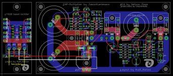
Thanks Rudi, can you help guide the AC power in connections on the layout posted in the first post of this thread. I see the LT4320 board on the left side and on this board I do not see the transformer secondary AC in where it goes as I can only see the AC out.
Coming to the capmx built in on the amp boards, I see the bridge rectifier but do not see where is the AC input wiring that is connected from the transformer secondary. May be I am missing something on the wiring/connections looking at the layout picture, sorry.
Rgds
For those preparing to build a new ACA, the ACA amp with premium parts thread is still active.
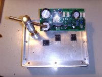
manniraj: I have attached a picture to show you, how to replace the onboard bridge rectifier by the LT4320-rectifier PCB (in case ?? you want to use the LT4320).
Connect one of your transformers secondaries to pole 1 resp. pole 4 of the 4-pole connector on the LT4320-PCB (yellow tracks on the picture).
Connect '~' and '+' and '~' and '-' on the ACA-PCB as shown on the picture (light blue tracks) by 2 solid cores.
Then run 2 wires from the LT4320 4-pole connector-poles "OUTP" and "OUTN" to the 2-pole connector, labelled "AC" on the ACA-PCB.
This is illustrated by the red and the white wire on the picture below.
I hope things are clear now.
Regards - Rudi
Attachments
Rudi, thank you for the idea of using wood, I have had this piece of South African Imbuia lying around to be used for another amp, but will use it for this.Photo below of wood panel - 12 mm thick.
Been hunting down some heeatsinks that were lying around. These will be perfect for the ACA, especially once they have been anodised - colour to be decided still, but will try and match to the wood.
Turns out all the components I could not get (FETs and BJTs) from the "Big Boy" suppliers are available from a company I only occasionaly use. Includes the 2SK170s - though roughly $7 (US) each. Hope they are the genuine article. Big thanks to Skylar88 for reminding me about them!!
The sinks are 120 mm long x 170 mm high (stacked) and 75 mm fin/plate depth. Base and top will be aluminium. I have some 15 mm square alu bar for the trafo to mount onto, and can be used to tie the two heatsinks together front and rear - top and bottom plates can then bolt to the sink and rods. Hmm a cube might look cool - I can get 25 mm square alu bar and make front and rear verticals to bolt the sinks together vertically - will also provide the depth required for the PCBs to fit in just nicely. The wood front and rear plates can bolt onto the 25 mm bar - put in a 2 or 3 mm PTFE shim to protect the wood from excessive heat. Wood can be sealed with bee's wax.
.jpeg")
.jpeg")


P.S. Can the IRFP240 be mounted with very short flying leads so that each is on one of the heatsinks, or should I just mount the PCB in such a way that they are as close to the centre as possible. I will have the heatsink flat lapped so that the joint is clean. Can of course just rotate the PCB so that it is vertical. vertically
Been hunting down some heeatsinks that were lying around. These will be perfect for the ACA, especially once they have been anodised - colour to be decided still, but will try and match to the wood.
Turns out all the components I could not get (FETs and BJTs) from the "Big Boy" suppliers are available from a company I only occasionaly use. Includes the 2SK170s - though roughly $7
(US) each. Hope they are the genuine article. Big thanks to Skylar88 for reminding me about them!! The sinks are 120 mm long x 170 mm high (stacked) and 75 mm fin/plate depth. Base and top will be aluminium. I have some 15 mm square alu bar for the trafo to mount onto, and can be used to tie the two heatsinks together front and rear - top and bottom plates can then bolt to the sink and rods. Hmm a cube might look cool - I can get 25 mm square alu bar and make front and rear verticals to bolt the sinks together vertically - will also provide the depth required for the PCBs to fit in just nicely. The wood front and rear plates can bolt onto the 25 mm bar - put in a 2 or 3 mm PTFE shim to protect the wood from excessive heat. Wood can be sealed with bee's wax.
P.S. Can the IRFP240 be mounted with very short flying leads so that each is on one of the heatsinks, or should I just mount the PCB in such a way that they are as close to the centre as possible. I will have the heatsink flat lapped so that the joint is clean. Can of course just rotate the PCB so that it is vertical. vertically
Last edited:
@cl00sed:
As I have already written: I do not have any experience with a transformer using the ACA - CAPMx-PSU and having a secondary with rating > 19VAC.
If I were you, I would order a 2 x 19VAC (or 2 x 20VAC) transformer rated at 200VA (meaning: max. >=5A per secondary).
Please do have a close look at TungstenAudios recommendations!
@Ferret: please mount the heatsink vertically, so the heat can travel unhindered from bottom to top!
Mount the TO-264 transistors (2 belonging to the ACA, 1 to the PSU) beneath the PCB, directly on the heatsink.
Regards - Rudi
P.S.: The picture attached is showing my 1st attempt using a full-bridge rectifier.
The rectifier needs to be mounted on the heatsink as well! Otherwise it gets very hot!
Attachments
Last edited:
That transformer with 22V secondaries should be a good choice for this project. Depending on the voltage lost in the synchronous rectifier and the CapMx, the voltage sent to the amp will be around 26 Volts. This is a good range for a pair of IRFP140 Mosfets. The 'bias' voltage should be set to half of this, plus 0.4V.
That transformer with 22V secondaries should be a good choice for this project. Depending on the voltage lost in the synchronous rectifier and the CapMx, the voltage sent to the amp will be around 26 Volts. This is a good range for a pair of IRFP140 Mosfets. The 'bias' voltage should be set to half of this, plus 0.4V.
So I can proceed with transformer 0-22v@150va (dual secondaries) order?
Regards
Raj
If 150VA for each secondary (300VA total), then yes.
Thank you, yes 300VA in total
Regards
If 150VA for each secondary (300VA total), then yes.
Thanks even I have the following transformer which I used earlier for my Sony VFET2:
Primary 0-230VAC
Secondary 1: 0-22v @ 6.8A
Secondary 2: 0-22v @ 6.8A
So a total of 300VA for 2 rails (secondaries) transformer.
- Home
- Group Buys
- Premium ACA with CapMX PSU