Nelson is obviously most expirienced around here so maybe he want to answer my question,when designing a preamp what you consider the worst case input dc-voltage (offset) that servo must remove? I`m thinking about the dc offset voltage that comes from the source to the preamps input.
Cheers Borko.🙂
I believe AndrewT was quite right. Today I measured the sample openloop. Servo series resistor : FB ground resistor was 270k : 3k9. The servo was easily able to maintain zero output offset, with opamp output DC voltage as low as 0.78V. Openloop gain is 80dB.
Regards,
when designing a preamp what you consider the worst case input dc-voltage (offset) that servo must remove? I`m thinking about the dc offset voltage that comes from the source to the preamps input.
For that I use a capacitor. A source that has DC doesn't
deserve better.
😎
Regarding the coupling caps, I used them, but switched to DC servos few years ago. I am with John here 😎
I use DC coupling too but somewhere has to be a protection cap. In my case i have it in front of the poweramp but it also has a filtering purpose. It is a very high quality 10nF nonmagnetic silver mica that makes together with the 330kOhm input impedance of the amps a 6dB filter for my midrange - treble baffles That praxis rescued my system many times because i do a lot of hot plucking and i can play very load without my midrange drivers bottoming.
this looks like something even more special!
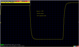
Do I see 45V/us into a resistor load and 25V/us while charging 15nF?
Do I see 45V/us into a resistor load and 25V/us while charging 15nF?
Both is RC exponential charging, not slew rate. My fast gen gives 2Vp-p max., so I do not know slew rate yet.
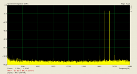
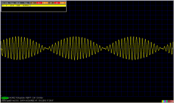
The previous measurement was for usual link level, a bit below 1V. Now the large signal, both in time and frequency domain. For the FFT, there is a resistor divider at the preamp output.
Attachments
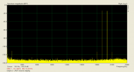
Analog scope is still the best one. Output cable terminated by 50 ohm, to eliminate reflections.
Attachments

Last edited:
What an answer! 😀For that I use a capacitor. A source that has DC doesn't
deserve better.
😎
PMA, the most important question, does it sounds better then bjt version and have you played with feedback factor, OL gain and bandwidth (resistive vas loading) and does this version with about 70dB feedback sounds best??
Cheers, Bogdan.
Cheers, Bogdan.
pma:
if you don't mind me asking, what was the design target open loop bandwidth for this gain stage?
mlloyd1
if you don't mind me asking, what was the design target open loop bandwidth for this gain stage?
mlloyd1
PMA, the most important question, does it sounds better then bjt version and have you played with feedback factor, OL gain and bandwidth (resistive vas loading) and does this version with about 70dB feedback sounds best??
Cheers, Bogdan.
Hi Bogdan,
yes, this JFET version 'sounds better' than the previous BJT version. The sound is more full/rich, natural. Highs have excellent resolution and clarity. The sound is more airy.
As I wrote in the BT thread, I have not found much consequence of feedback to sound 'quality'. IMO there is no universal answer and everything strongly depends on the circuit. I am sure that the bad reputation of feedback results from application of feedback to low slew rate, high distortion and low idle current O/P circuits. In these cases, sound remains horrible and only THD numbers are improved.
A year ago I designed Dispre 3, the no global feedback BJT version. After tests and comparisons, I have definitely burried this version month ago. Compared to pre standard II and Dispre 2 - JFET, the Dispre 3 non-global NFB was harsh, agressive, and with poor resolution.
To summarize - I have not found any rule between FB factor and sound if the circuit inside feedback is very fast, high slew rate, linear and class A, and OLG corner is several kHz.
Best regards,
Last edited:
I would like to speak a bit about design goals of this project.
Engineering
1) excellent linearity even at high frequencies
2) inherently very fast, very high slew rate
3) very stable
4) low noise
5) class A output stage
Subjective
6) very good sound
I believe all the goals were achieved. I have already shown CCIF IMD results, which are below my measurement threshold for practical link level output.
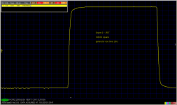
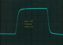
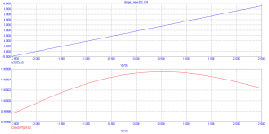
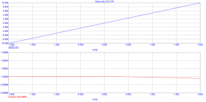
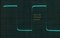
Now i would like to add simulation comparison of Dispre 2 vs. Dispre 2 - JFET static linearity. They are for output voltage range -10Vp to +10Vp. Red line shows normalized dVout/dVin, i.e. normalized gain vs. input voltage. Blue line shows output voltage vs. input voltage. Finally I attach 100kHz square response, without capacitor in an input RC filter. In this case, the preamp has 3.68MHz -3dB corner. This will be reduced at some 200kHz by input RC filter.
Engineering
1) excellent linearity even at high frequencies
2) inherently very fast, very high slew rate
3) very stable
4) low noise
5) class A output stage
Subjective
6) very good sound
I believe all the goals were achieved. I have already shown CCIF IMD results, which are below my measurement threshold for practical link level output.
Now i would like to add simulation comparison of Dispre 2 vs. Dispre 2 - JFET static linearity. They are for output voltage range -10Vp to +10Vp. Red line shows normalized dVout/dVin, i.e. normalized gain vs. input voltage. Blue line shows output voltage vs. input voltage. Finally I attach 100kHz square response, without capacitor in an input RC filter. In this case, the preamp has 3.68MHz -3dB corner. This will be reduced at some 200kHz by input RC filter.
Attachments
Last edited:
- Home
- Source & Line
- Analog Line Level
- Preamplifier Dispre 2 - JFET