apassgear said:
Why should you need an input cap?
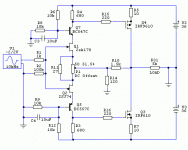
If you look at the pic of the preamp you'll see no input cap - I don't use it, it's a matter of personal decision.
But I published the schematic and I feel responsible for well-being of less experienced member's woofers - people use diifferent sound sources - my TV, for example, puts out 3V DC 😉
Hi Juma
Can you post a pic of the pcb traces? I would like to give your circuit a try but my attempts at laying out pcbs often resulting in loud humming

Can you post a pic of the pcb traces? I would like to give your circuit a try but my attempts at laying out pcbs often resulting in loud humming


npapp said:
Can you post a pic of the pcb traces?
I used pcb layout from post #3 of this thread, just changed component values according to schematic in post #53 and output pair is BJT, not JFET (S=E, G=B, D=C)
juma said:After few months of experimenting here is the circuit that sounds best to me - it's the same topology as the first one in this thread but with BJTs in output and higher Id through JFETs (6ma).
It takes the +/- 24V from F5 (they are both in the same case - F5 as integrated amp)
juma,
Isnt 24 Volt a bit high for the 2SJ74 fet.
Had any issues?
Lineup, if you look closely at the sch. in post #53 you'll see that JFETs are supplied with +/- 12 V 😉
lineup said:
Isnt 24 Volt a bit high for the 2SJ74 fet.
Datasheet says Vgd=25V. Why are you concerned? I have reed here in forums, that this 25V is very conservatively stated.
juma-- do you think this preamp would work well built into an F4? and i have a B1 for volume control duty, could i just leave off the 10k pot? how would i implement that ? thanks bubba177
bubba177 said:juma-- do you think this preamp would work well built into an F4? and i have a B1 for volume control duty, could i just leave off the 10k pot? how would i implement that ? thanks bubba177
Not as it is because F4 needs ~22V peak input for full output. F4 already has built in JFET buffer so it doesn't need B1.
In fact, with circuit below you can lose input JFETs from F4 and connect the output of this preamp directly to point where C1 and C2 (F4 sch.) are connected.
Attachments
thanks juma-- i normally listen to my B1 and F5--when i put in my F4 it plays with the B1 but i wish i had three more clicks on the volume control--i have been looking for something ( gain stage) to install in the F4 and run off of it's 24v rails.
Of course you can run it from 24V rails, but it won't drive F4 to full power. If you can accept that compromise, use 78L18 and 79L18 regs (instead od 7xL12) in circuit from post #53, change R9 to 220 Ohms and you can expect clean ~16V peak output which will suffice for about 32 W/8 Ohms peak (16 W avg.) on F4's output.
Hi Mark,
20k in that position is hard to imagine 😉
Standard resistance markings are:
1k means one kiloOHM,
1M stands for one megaOHM,
1R or 1E or just simple 1 is one OHM.
Also, there is 100m - 0.1 OHM i.e. 100 miliOHMs
So, that pot (P1) is 20 OHMs - JFETs don't have to be absolutely matched, but keep them in the same Idss class (preferably BL, but if jou have V grade JFETs you can make that pot 47 or 50 OHMs).
Have fun !
juma-circuit from post 53 with the changes mentioned in post 72 is what i use to drive my F4--correct? circuit in post 70 confuses me-i don't even see an output-dumb in missouri ( show me state)
The post #72 refers to circuit in post #53. The changes are intended for driving F4 better with that circuit.
The circuit in post #70 is intended for driving F4 to full power. It should have higher PSU (+/- 32 to 36V). Its ouput is taken from MOSFETs' drains. R31(5K) is not the part of the circuit - it just represents the load i.e. the amp that it is driving.
The circuit in post #70 is intended for driving F4 to full power. It should have higher PSU (+/- 32 to 36V). Its ouput is taken from MOSFETs' drains. R31(5K) is not the part of the circuit - it just represents the load i.e. the amp that it is driving.
- Home
- Amplifiers
- Pass Labs
- Preamp ideas for F5
