Yes, Certainly. I beleive the article actually does not connect the output to the output stage does it?
😉
😉
Hello Mr. dB and flg. The schematic of the input board for BA3 shows it to be a Transconductance Amplifier [TCA]. Its output has opposed drains and it is void of loop feedback. diyAudio is a fertile ground to share new ideas, and to experiment with the proposed devices. Conventional wisdom has its place. But nothing [unless unsafe] should be cast in stone. The thinking that this is how it was, is, and will always be done is unhealthy and a counter productive approach for this hobby. For example; who would have guessed that Mr. Pass will ever use an interstage transformer in a power amp like F6? He never used this approach before; knowing the ills attendant to a transformer..Yes, Certainly. I beleive the article actually does not connect the output to the output stage does it?
😉
I continue to enrich my two topics in Headphone Systems to be commensurate with my philosophy above. Best regards.
Pardon me for being dense, but do I understand correctly that some people are suggesting the BA3 input board for a line-stage preamp?
I used it as a preamp for my F5, and it is sweet. The soundstage is very wide.
Personally i felt the magic isnt there when i put it in a F4.
Last edited:
neoinc,
Did you drop the input Jfets on the F4? THis would make it a true BA3. Intersting that you like it in front of F5. Might have to try that. Seems like you are hearing the F5 and not the BA3 FE.
Did you drop the input Jfets on the F4? THis would make it a true BA3. Intersting that you like it in front of F5. Might have to try that. Seems like you are hearing the F5 and not the BA3 FE.
neoinc,
Did you drop the input Jfets on the F4? THis would make it a true BA3. Intersting that you like it in front of F5. Might have to try that. Seems like you are hearing the F5 and not the BA3 FE.
The jfets were taken out for F4. However i do put a B1 infront of BA3 for volume control. Imho, F5 need good pre-amp, a B1 is not good enough to enjoy the F5.🙂
I did not like the B1 in front of the BA3. MY favorite was Salas 6V6 in front of BA3. I do in fact like the DCB1 in front of the F5T. Good synergy. Throw volume pot on front of BA3. No need for B1.
...The schematic of the input board for BA3 shows it to be a Transconductance Amplifier [TCA]. Its output has opposed drains and it is void of loop feedback...
Yes, this would be true but, by saying that, you are indicating, like a current source, it has high output impeadance. It does not. The output is loaded heavily effectively changing it to a voltage source.
Thanks buzzforb, i am thinking of putting a volume knob too but should i put it infront or after the ba3? Is 10k pot good enough?
Hello buzzforb and neoinc. My philosophy for diyAudio is like yours. Experiment, experiment etc. Best regards.I used it as a preamp for my F5, and it is sweet. The soundstage is very wide.
Personally i felt the magic isnt there when i put it in a F4.
Thanks buzzforb, i am thinking of putting a volume knob too but should i put it infront or after the ba3? Is 10k pot good enough?
In front of Ba3, IMO. 10k is good, as you have Ciss of input Jfets and Mr Miller to deal with.
Yes, this would be true but, by saying that, you are indicating, like a current source, it has high output impeadance. It does not. The output is loaded heavily effectively changing it to a voltage source.
The definition of a voltage source amp can be a grey area. The output Z of a TCA need not be a very high value like >100 Ohms. For example, the several F-type TCAs in www.firstwatt.com have an output impedance ranging from 15-80 Ohms. The definition of a voltage source amp in my book is straightforward. The output is taken out of transistors connected in the common drain configuration; meaning opposed emitters; with, and without an attendant loop feedback. This is a classical definition. Another example in ACA#1. Its output transistors are opposed drains of MOSFETs; meaning an operating common source configuration. It has an output impedance of 10 Ohms in the abscence of loop feedback, and thus is a pure TCA in my book. Loop feedback lowers this TCA's output impedance a bit further; but not enough where it is <0.1 Ohm like a true voltage source amp. In my book, ACA#1 is a hybrid TCA-VSA. It embodies the best of both worlds to express its magic.
Tinitus, read the post #221. R6 is a part of voltage divider that sets the Vgs and it can't be 1M because the other part of that divider (R5) sets the gain with R7(which determines the Zin).
Go 22 posts back in this thread and read from there on...
Anyway I made a better version of that preamp:
MOSFET-trioda Mju folover verzija - Solid State - diyaudio.rs
Is it possible to let the two 1M resistors (one from each channel) share a common bias voltage (like in B1)?
Absolutely. Just take care with the layout.Is it possible to let the two 1M resistors (one from each channel) share a common bias voltage (like in B1)?
The definition of a voltage source amp can be a grey area. The output Z of a TCA need not be a very high value like >100 Ohms. For example, the several F-type TCAs in www.firstwatt.com have an output impedance ranging from 15-80 Ohms. The definition of a voltage source amp in my book is straightforward. The output is taken out of transistors connected in the common drain configuration; meaning opposed emitters; with, and without an attendant loop feedback. This is a classical definition. Another example in ACA#1. Its output transistors are opposed drains of MOSFETs; meaning an operating common source configuration. It has an output impedance of 10 Ohms in the abscence of loop feedback, and thus is a pure TCA in my book. Loop feedback lowers this TCA's output impedance a bit further; but not enough where it is <0.1 Ohm like a true voltage source amp. In my book, ACA#1 is a hybrid TCA-VSA. It embodies the best of both worlds to express its magic.
My apology flg. I mispoke [miswrote] regarding the underlined above. The output stage MOSFETs in ACA#1 are not opposed drains.
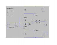
After few months of experimenting here is the circuit that sounds best to me - it's the same topology as the first one in this thread but with BJTs in output and higher Id through JFETs (6ma).
It takes the +/- 24V from F5 (they are both in the same case - F5 as integrated amp) and preamp's OUT is connected directly to F5's input.
I used the PCB from the post #3 of this thread but with some diferent components and values.
What is it about the sound of this pre - that you prefer over the differential pair version ?
Does adding a current mirror, to the differential pair, help with the matching of the jFET's ?
I'm wondering about how much audible noise those carbon variable resistors add.
If the 10K volume control is at the front of the pre, the noise would get amplified by the pre and power.
So I'm wondering if the volume control should be placed between the pre and power amp.
.
Uu buddy,
the only absolutely valid (for you) answers on your questions are just a couple of hours of work/fun away from you. Build it, test it, enjoy it - or discard it.
Anyway, that's the only way to know your truth - some of your question have subjectively influenced answers, some are tiringly debatable (I'd never put a pot between the preamp and the amp but I'd rather bite my leg off than to defend that stand for the 137th time).
So, in the end, it's up to you... 😉
this pre has only J-fets? sorry. have not followed lately.
i use aleph 1.7 now. but gonna try j-fet boz and all fet cascoded borbely🙂
i will try 10K and 50K on the input and outputs of those two🙂
on the aleph, you dont want it on the input🙂
i use aleph 1.7 now. but gonna try j-fet boz and all fet cascoded borbely🙂
i will try 10K and 50K on the input and outputs of those two🙂
on the aleph, you dont want it on the input🙂
What is it about the sound of this pre - that you prefer over the differential pair version ?
Does adding a current mirror, to the differential pair, help with the matching of the jFET's ?
I'm wondering about how much audible noise those carbon variable resistors add.
If the 10K volume control is at the front of the pre, the noise would get amplified by the pre and power.
So I'm wondering if the volume control should be placed between the pre and power amp.
.
You said that you've spent a months experimenting and here is the circuit that sounds best to me
So I legitimately ask you what it is you like this version, over the differential pair version, and you just about soil yourself.
The questions about the current mirror and location of the volume pot were pretty reasonable too.
Don't f**king bother.
Uu, it was years ago and I've built more than a dozen of different preamps since then. You can't expect me to remember all of the details how it sounded to me in that time - what was true to me then still stays written.
P.S. No need for harsh language, I'm not your employee - what I had, I gave. What's your contribution here ?
P.S. No need for harsh language, I'm not your employee - what I had, I gave. What's your contribution here ?
Last edited:
- Home
- Amplifiers
- Pass Labs
- Preamp ideas for F5