It is not impossible to achieve gain 40 dB (100x), in this case you need to decrease value of resistor between emitters of input pair to some 20 Ohms. But distortion will get into percents, i.e. 100x higher than original circuit.
I would recommend no more gain than 30 dB (30x approx.), this is for resistor 200 Ohms between emitters of input pair. You will have to play DC game again.
I would recommend no more gain than 30 dB (30x approx.), this is for resistor 200 Ohms between emitters of input pair. You will have to play DC game again.
I see.
How about making 2 "preamp concept" in series, each have gain of 10 (that makes total =100X), will this have the same "percent" distortion?
If it is the same, it is better to make 1 with 100X gain, due to simplicity.
This is difficult for me to decide, since the whole thing is non-feedback, distortion raise is confusing 😀
David,
I did not intend to reach gain 40 dB when I designed this circuit.
You can try to connect 2 in series, but not DC coupled. AC coupling by input capacitor before 2nd circuit would be necessary.
I did not intend to reach gain 40 dB when I designed this circuit.
You can try to connect 2 in series, but not DC coupled. AC coupling by input capacitor before 2nd circuit would be necessary.
Hi, PMA,
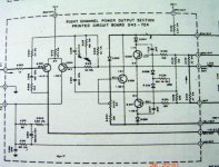
This is the McIntosh schematic that makes me think about transistor based ccs. The final's voltage is +/-35V.
If you notice in the attachment, something is strange. The output rail is only +/-35V, but McIntosh loaded the differential with 47k to +105V and load the VAS with 3k6 to +100V.
It is certainly more difficult and more costly to make additional 105V, just to drive 2 nodes with small mA requirement, compared to making transistor based ccs that can work from 35V.
If it is not important reason, I'm sure they won't do it. But they do it the hard way.
In your opinion, why McIntosh do it the hard+expensive way?
Attachments
PCB Board
Hello PMA,
do you have any preamp DISPRE news for us ?
Can you publish the PCB on you Website ?
Next i will build a new and my first line driver...
Many thanks.
Hello PMA,
do you have any preamp DISPRE news for us ?
Can you publish the PCB on you Website ?
Next i will build a new and my first line driver...
Many thanks.
Hi Uwe,
there is nothing especially new, after listening presentation in our hifi community the preamp has been quite successful here in CZ, 14 assembled boards were sold after 1st announcement, and very well rated. For that reason, I will not publish the PCB files.
Best regards,
Pavel
there is nothing especially new, after listening presentation in our hifi community the preamp has been quite successful here in CZ, 14 assembled boards were sold after 1st announcement, and very well rated. For that reason, I will not publish the PCB files.
Best regards,
Pavel
Hi Uwe,
http://web.telecom.cz/macura/dispre.jpg - is more than enough 😀Can you publish the PCB on you Website ?
Hi Pavel,
I have a very technical question: "Why did you use one Philips head bolt that doesn't match the others?" 😀
BTW, I prefer Allen head. 😉
regards
I have a very technical question: "Why did you use one Philips head bolt that doesn't match the others?" 😀
BTW, I prefer Allen head. 😉
regards
Greg Erskine said:Hi Pavel,
I have a very technical question: "Why did you use one Philips head bolt that doesn't match the others?" 😀
BTW, I prefer Allen head. 😉
regards
Hi Greg,
just took something available from my component shelf 😀
I made PCB for DisPre, today. I can post only top view. Need to ask Pavel for the rest 🙂.
ps: Greg, how are You?
Boban
An externally hosted image should be here but it was not working when we last tested it.
ps: Greg, how are You?
Boban
Hi Boban,
Nice looking layout as usual. 😀 It will be nice to see the tracks if Pavel says its OK then we can really see.
ps: I'm going fine thanks, hope you and your family are well. 😉
regards
Nice looking layout as usual. 😀 It will be nice to see the tracks if Pavel says its OK then we can really see.
ps: I'm going fine thanks, hope you and your family are well. 😉
regards
...
There are some problems with file hosting server. Here we go again:
Boban
There are some problems with file hosting server. Here we go again:
An externally hosted image should be here but it was not working when we last tested it.
Boban
update...
Today I put this board in action... Oh my, this preamp sounds fantastic !!! Just that, nothing more,nothing less! Great preamp Pavel. Thanks for the circuit
  .
.
Boban
Today I put this board in action... Oh my, this preamp sounds fantastic
!!! Just that, nothing more,nothing less! Great preamp Pavel. Thanks for the circuit .Boban
One more thing, forget to ask.
I measure on emiters resistors (R11 or R12) only 24.3mV, I=9mA. How can I get 20mA, whta need to change? Pavel?
Thanks in advance.
Boban
I measure on emiters resistors (R11 or R12) only 24.3mV, I=9mA. How can I get 20mA, whta need to change? Pavel?
Thanks in advance.
Boban
Just reduce value of those emitter resistors. I am sorry I cannot participate in discussion very much just for the reason of being too busy now. Please send me an e-mail in case you have serious questions, and please be patient in waiting for my reply.
Rgds,
Pavel
Rgds,
Pavel
Hello!
Help Please!
What are values of caps C7, C15, C8, C9, C10, C16?
They seem to be decoupling caps, tantallum?
But what are he values?
😕 😕 😕 😕 😕

Help Please!
What are values of caps C7, C15, C8, C9, C10, C16?
They seem to be decoupling caps, tantallum?
But what are he values?
😕 😕 😕 😕 😕
- Status
- Not open for further replies.
- Home
- Amplifiers
- Solid State
- Preamp concept