Hi, PMA,
Thanks. What is the resistors value to be changed when I wanted to tailor the Vout/Vin gain?
I really remember you have wrote about those 2 explenation, but where is it?
About changing CCS by bootstrapp. When I try to overcome oscilation (in another amp), I somehow got an impression that using even a single transistor is not as easy as I've always think it is. Many clues that in practice, transistor have their "hidden" personalities.
For example, there is a case of local oscilation, that doesn't occur at one bias point, just raising the bias, then it becomes oscilates. Oscilation of plain darlington. Oscilation of CFP. Oscilation of cascodes. Oscilation of super pair. Varying impedance of CCS. I try to search for answer here, found something like "negative base impedance" "base stoppers", "complex number (i,j) base impedance-not linear with frequency", "early effect", "non-linear transistor transfer function", etc. I also found out that although audio power amps only tobe processing signal below 20khz, even 10's of Mhz behavior of the transistor cct will impact the audio amp audibly.
This makes me think that a plain resistor (yes, that cheap one) is more predictable in behavior. It won't have complex number (i,j) frequency dependant.
Some designers using R only for ccs, many reports that they sounds better. McIntosh even forces to use resistor for ccs, to get linearity they push the rail so high and use big valued resistor, but they still don't use transistor based CCS, even in the books they perform better, have better PSRR.
In some places, plain resistor is not that good, it has to have aid from bootstrapp, performing a kind of CCS for AC signal. Bootstrapped also making a tight connection between in (or intermediate stage) to the output, AC'ly.
Yes, this tought makes the design looks like back to the amp from 50's or 60's, stone age, but I don't care.
That is what I think. You can think differently, offcourse 😀
In this case, I'm looking for your opinion. If you say it's better to use transistor based CCS, then fine, I will follow you. 😀 Because this (these) are your design(s), you should be understand more about them than myself.
David,
regarding post No. 50, the gain is set by resistors R1 + R2. The greater resistor value, the lower gain.
regarding post No. 50, the gain is set by resistors R1 + R2. The greater resistor value, the lower gain.
Hello PMA,
i don't know how to exact calculate the gain of the first diff stage Q1,Q2 Re=4k7(R3,R4) Rc=200(R5,R6) and
the second Stage Q3 Re=200 (R5) Rc=4k7 (R7).
Can you please explan that ?
Many thanks.
Now i run the complet preamp with the Input stages and my changes to +/-20 V power supply.
Thank you for the new ideas !
PMA said:regarding post No. 50, the gain is set by resistors R1 + R2. The greater resistor value, the lower gain.
i don't know how to exact calculate the gain of the first diff stage Q1,Q2 Re=4k7(R3,R4) Rc=200(R5,R6) and
the second Stage Q3 Re=200 (R5) Rc=4k7 (R7).
Can you please explan that ?
Many thanks.
Now i run the complet preamp with the Input stages and my changes to +/-20 V power supply.
Thank you for the new ideas !
dx.master, i would very much like to see your 20v implementation, but the link doesn't work 🙁
Hi PMA, thanks for posting your design. I have been looking for something like this for a loooong time! There are a few things I don’t understand about it, though (actually a lot – but none of it is your fault – I am just a rather inexperienced with this stuff.). If you don’t mind, could you please enlighten me on a couple of points:-
1) Why are there 2 resistors at R1 & R2?
2) Is R21 a trimpot?
3) Why did you choose to use the (inverting?) input that would normally be used to accept the NFB?
4) I have a dual supply I would like to use. (16v regulated and 20v unregulated). How would you suggest implementing it?
5) I shall have to attempt this using stripboard. Do you have any points that I should bear in mind re layout etc.?
Thanx.
Ups wrong link
Hello hihopes,
Ups wrong link !
Now i run the complet preamp with the Input stages and my changes to +/-20 V power supply.
I make some pictures of my testboard, that you can see here[URL].
All the best, Uwe
Hello hihopes,
dx.master, i would very much like to see your 20v implementation, but the link doesn't work
Ups wrong link !
Now i run the complet preamp with the Input stages and my changes to +/-20 V power supply.
I make some pictures of my testboard, that you can see here[URL].
All the best, Uwe
hihopes said:
1) Why are there 2 resistors at R1 & R2?
2) Is R21 a trimpot?
3) Why did you choose to use the (inverting?) input that would normally be used to accept the NFB?
4) I have a dual supply I would like to use. (16v regulated and 20v unregulated). How would you suggest implementing it?
5) I shall have to attempt this using stripboard. Do you have any points that I should bear in mind re layout etc.?
Thanx.
Hi hihopes,
I would rather speak about final schematics that can be found in post
http://www.diyaudio.com/forums/showthread.php?postid=748755#post748755
Regarding your questions referred to post No. 50, values.gif image:
ad 1) R2 is a trimpot to match gains of 2 channels (see my web page)
ad 2) R21 are 2 resistors in series (see my web page)
ad 3) the input is non-inverting. Q1 inverts, Q10 inverts again and output buffer does not invert.
ad 4) use bridge, 2 x 3300uF caps and 7815 + 7915 stabilizers.
ad 5) no, I have not. I made the first prototype on stripboard as well.
Uwe,
there is some problem in the way you are creating your links. I will try to repair one of them. Do not forget to write "/" before last "url" in the brackets.
... Trying my best but it does not work ...
there is some problem in the way you are creating your links. I will try to repair one of them. Do not forget to write "/" before last "url" in the brackets.
...
Trying my best but it does not work ...dx.master said:Hello PMA,
i was to late for edit this post.
here is the correct http://bauteile-fur-die-elektronik....eamp_concept/index.php?folder=/dx.master/eval.
The Project website can be found http://bauteile-fur-die-elektronik.akadns.de/projekte/PMA_Preamp_concept/index.php.
Hi Uwe,
They still do not work when I try them. I edited them in this reply (hereabove), let's see.
P.S. I thought there was a problem with german ű (ue), so I tried only u (fűr, fuer, fur). It still does not work. Anybody having luck to open new links from dx master?
correction
MAP, Ups, all link work for me.
please try this:
- project page: http://bauteile-fuer-die-elektronik...A_Preamp_concept/index.php?folder=/dx.master/
- test board: http://bauteile-fuer-die-elektronik...eamp_concept/index.php?folder=/dx.master/eval
what about the Link at the bottom of this website: "WWW"
will this on working ?
I have just tried them, but alwyas got reply "could not locate remote server". Reply from another forum member would help greatly.
PMA said:I have just tried them, but alwyas got reply "could not locate remote server". Reply from another forum member would help greatly.
Hmmm, links work for me. I'm using Firefox, if that's any help.
Take
Please Check this out
Hello @tester:
Please Check this link:
http://dx.master.akadns.de/projekte/PMA_Preamp_concept/index.php?folder=/dx.master
Hello @tester:
Please Check this link:
http://dx.master.akadns.de/projekte/PMA_Preamp_concept/index.php?folder=/dx.master
Okay - I believe that Uwe will solve the link problem. I assume we could better return to the topic 😉
Hi, PMA,
In your English page, you wrote this preamp concept has -3db bandwith of 7hz-3Mhz. This is good, very good.
Is it flat linear from 7hz-3Mhz without flaws in that bandwith?
I still wanted to implement this idea for power amp front end. For power amp (with volume pot infront), I will need about 50x gain. For the extreme, is it OK to set this preamp concept for fixed gain of 100x, for example? Or it is not good to set the gain this high?
Hi, PMA,
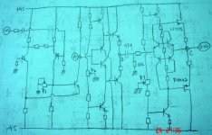
I've given the idea (of making "preamp concept" to openloop power amp, still have the original spirit of non feedback) many tought.
First, R7 (4k7) is not changeable to bootstrapped. It has to stay a pure resistor.
Second. About the DC offset you raised. You are right. So in this sch, I introduce 3 pots to set DC offset at 3 important points.
P1 is for adjusting DC at point A. P2 is for adjusting DC at point B. P3 is for adjusting DC at point C (output). P2 and P3 is setting the bias balance for lower/upper current sources.
I've included 47uF cap coupling + 10k before the NP-PMA. This looks like a more implementable amp.
I still have not clear, wheter it is wise to set the front end gain up to 100X. It is wise to do so? I don't want to use any additional preamp, just a potentio volume control in the enter point. So the gain should be 50X at least.
I think NP-PMA can give the low output impedance like ordinary feedback to inputstage, (even it is openloop without feedback, )because it is a full differential feedback itself (in follower mode).
Attachments
David,
I believe that your last one should work. Regarding P1 pot for DC setup, I would recommend to split it in a fix resistor + trim pot, the trim pot value should be considerably lower than that of fix resistor, otherwise DC at collector of 3rd transistor will dramatically depend on every touch of pot's turning screw.
You do not need the P2, as DC at point B is completely set by P1.
- Status
- Not open for further replies.
- Home
- Amplifiers
- Solid State
- Preamp concept