Sorry, you are right. Small capacitors are 100nF ceramics. Electrolytes are 1000 uF (see photo of the preamp).
Pot is 5k or 10k. Do not go higher than 10k.
Pot is 5k or 10k. Do not go higher than 10k.
MaxS,
I have made my audiopage working again 😉 .
But I have to apologize to the readers - sometimes I am really not able to respond, being pretty engaged in my professional projects ...
I have made my audiopage working again 😉 .
But I have to apologize to the readers - sometimes I am really not able to respond, being pretty engaged in my professional projects ...
Oh one more thing what's the connection for little pots. Which lead is connected to the regulation (trim lead)?
and does it matter if 1 or 3 is first?
and does it matter if 1 or 3 is first?
The small trimpots (R9 and R25, or R2 in "values.gif") are used for fine setting of gain - to match gain of both channels. They work as variable resistors, you do not have to care how to connect the middle pin - left or right end, does not matter.
I understand that the value that has to be set by these vresistors is 20 mA as shown in the schematic?
I wonder why have you put R42 and R38 together instead of one resistor?
I bet it's because U had such values in stock😀 .
Or is this value to be realy precise 1K97.
I thought about putting there 1K91 ( I can get this value) and it will be within 1% tolerance.
Am I clever
I bet it's because U had such values in stock😀 .
Or is this value to be realy precise 1K97.
I thought about putting there 1K91 ( I can get this value) and it will be within 1% tolerance.
Am I clever
These resistors set DC at Q3 collector. It is easier to do it by 2 in series than by 1, as the value has to be set quite precisely.
Pavel
I have another question>
What if I changed in-capacitors and out-cap value.
e.g I would like to put there black gates N but there are no such values.
And does the in cap is not as important as out cap.
According to the picture you have put odinary mkp (wima?)cap at the input.
Wouldn't it be better to put pot instead of one of resistors for DC setting?
If you change these values, make them higher, never lower. The choice of cap types is up to you.
Pavel.
I would like to know what is your idea for using ordiary cap at the input and a BIG one at the out put.
What may change in the sound if we would put a Big one at the input?
I am preparing PCB😀 😀
I would like to know what is your idea for using ordiary cap at the input and a BIG one at the out put.
What may change in the sound if we would put a Big one at the input?
I am preparing PCB😀 😀
marsel said:Pavel.
I would like to know what is your idea for using ordiary cap at the input and a BIG one at the out put.
What may change in the sound if we would put a Big one at the input?
I am preparing PCB😀 😀
marsel said:How high can I go with the value of output caps as not to cut the low frequencies too much. 😕
I used the size of caps as I had them on stock. I am not about to discuss the "big" and the "small" ones.
Regarding low frequency corner, it can be calculated as:
F(low) = 1/(2 x 3.14159 x Rload x Cout)
I really do not have time enough to reply such questions.
Nexus said:Hello Pavel,
is there a pcb available for this preamp?
Best Regards:
Nexus.
🙂
The PCB production data exist. About 30 pcs were produced, 15 sold as assembled boards and 15 as bare PCBs.
At the moment I have no PCB on stock and do not plan to start new production soon. The DIY support is very time consuming, and I cannot spend that much time doing that, I am quite busy in my professional projects.
Please excuse me Pavel you are indeed very pacient reading to all my questions

But do you think that there can be some upgrade.
This thread h makes me really think...
http://www.diyaudio.com/forums/showthread/t-76229.html
But do you think that there can be some upgrade.
This thread h makes me really think...
http://www.diyaudio.com/forums/showthread/t-76229.html
PMA said:I am thinking about building a new preamp. The concept is shown in the attached image.
It is of interest, perhaps, that, contrary to popular opinion, your preamplifier's second stage is a severely unbalanced differential amplifier and not the common-base element of a complementary cascode.
This imbalance is responsible for the relatively poor forward gain obtained with this arrangement.
Re: Re: Preamp concept
Michael,
you are absolutely right. And you are also right that it is not much of interest for me, i.e. I am not going to modify it at all. This preamp had covered a kind of "social demand" 😉
Regards,
Pavel
mikeks said:
It is of interest, perhaps, that, contrary to popular opinion, your preamplifier's second stage is a severely unbalanced differential amplifier and not the common-base element of a complementary cascode.
This imbalance is responsible for the relatively poor forward gain obtained with this arrangement.
Michael,
you are absolutely right. And you are also right that it is not much of interest for me, i.e. I am not going to modify it at all. This preamp had covered a kind of "social demand" 😉
Regards,
Pavel
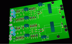
marsel said:Hello!
Here is my version of dispre PCB😀 😀 😀
Any comments? Every suggestion will be welcomed!!!!
Nice board, Marsel.
Looking forward your results.
Regards,
Pavel
- Status
- Not open for further replies.
- Home
- Amplifiers
- Solid State
- Preamp concept