Still no luck. I am getting a 100mV offset across 250K resistor ( and with no load ). I am just connecting two batteries of 9V in series and using the center tap as ground. Is that the problem the voltage difference in batteries causing an offset to appear at output?
Im sorry this has probably been answered before but can this buffer be made to drive a 600ohm headphone? If not how can it be scaled?
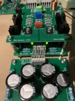
For my work in progress preamp, I've chosen for the Calvin buffer in combination with a Jung Didden superreg. The combo is supplied by a CRCRC quasimodo snubbered dual bobbin super fast soft recovery dual diode bridge, PSU.
The layout is done that way that the sense connections for the superreg are connected as close as possible to the semi power BJT's (2SA1209+2SC2911).
Bias current throught the 2SK389 is 6ma and throught the 2SA1209/2SC2911, 25mA.
With the trimmer it is easily possible to adjust DC offset to below 10µV.
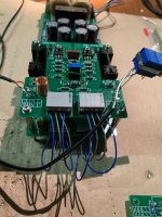
Below the pictures for a one channel setup, temporarily connected to test.
There will be 4 of these PSU in the preamp. 2 for the Calvin buffers, another one for a Muses 72320 volume control and one other for the input selection PCB.
The layout is done that way that the sense connections for the superreg are connected as close as possible to the semi power BJT's (2SA1209+2SC2911).
Bias current throught the 2SK389 is 6ma and throught the 2SA1209/2SC2911, 25mA.
With the trimmer it is easily possible to adjust DC offset to below 10µV.
Below the pictures for a one channel setup, temporarily connected to test.
There will be 4 of these PSU in the preamp. 2 for the Calvin buffers, another one for a Muses 72320 volume control and one other for the input selection PCB.
Attachments

Last edited:
correction above post
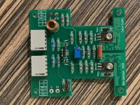
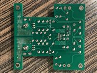
With soldering the second channel, I realized I've written an error. The output devices are 2x 2SA1209 instead of 2SA1209 and its complementary 2SC2911.
Some SMD devices are mounted on the underside.
With soldering the second channel, I realized I've written an error. The output devices are 2x 2SA1209 instead of 2SA1209 and its complementary 2SC2911.
Some SMD devices are mounted on the underside.
Attachments
Hi,
congrats, You just received a ´Calvin-approved´ for a well looking layout *rotfl*
jauu
Calvin
congrats, You just received a ´Calvin-approved´ for a well looking layout *rotfl*
jauu
Calvin
do you have spare PCB's or Gerber for getting made?correction above post
With soldering the second channel, I realized I've written an error. The output devices are 2x 2SA1209 instead of 2SA1209 and its complementary 2SC2911.
Some SMD devices are mounted on the underside.
thanks
kannan
Hi Kannan,
I have some boards left, but sending to Texas would be too expensive.
Below you can find gerbers of Calvin buffer, Jung didden superreg and PSU. IIRC all component values are mentioned on the silkscreen.
Regards
I have some boards left, but sending to Texas would be too expensive.
Below you can find gerbers of Calvin buffer, Jung didden superreg and PSU. IIRC all component values are mentioned on the silkscreen.
Regards
Attachments

Thanks BensenHi Kannan,
I have some boards left, but sending to Texas would be too expensive.
Below you can find gerbers of Calvin buffer, Jung didden superreg and PSU. IIRC all component values are mentioned on the silkscreen.
Regards
appreciate your help
kannan
I was just taking a look at the push-pull (modulated ccs) buffer. With 100 ohm load and 10Vp-p output, the 2nd harmonic still dominates at -80dB in respect to the fundamental of 20KHz. It has "second harmonic character", although I consider the distortion quite low. The 5th harmonic is better than -120dB and the 7th is -160dB. As shown, the bias is 8mA in the jfet and 75mA in the pnp. What a beauty.
edit: 2SA1381 is not adequate, it won't sustain hfe (beta) at 100mA. It's ok for simulation purposes. For construction, Q1 and Q2 are TBD


edit: 2SA1381 is not adequate, it won't sustain hfe (beta) at 100mA. It's ok for simulation purposes. For construction, Q1 and Q2 are TBD
Last edited:
Hi,
why not decrease the idle current by increasing R_top and R_bottom?
50mA (45+5mA) would be fully sufficient for 10Vpp into 100R.
Reducing the Id of the SK170BL to say 5mA/45mA would also reduce the heat power loss considerably (which is alot higher than in the cascoded JFETs of the Calvin-Buffer).
If You want run the circuit that hot, You might use a different PNP (plus possibly different compensation caps).
MJE350, 2SA1358, 2SA1837, 2SA1859, 2SA1930(!), BD140, KSA1220, ZTX750, ZTX957 et al.
jauu
Calvin
this is quite the same as Black Forest Buffer search bfb on diyaudio
suitable transistor TTA004B
suitable transistor TTA004B
The Black Forest Buffer was named after its original inventor, namely our most respected Calvin.
https://www.diyaudio.com/community/threads/the-diyaudio-first-watt-m2x.321925/post-6524985
https://www.diyaudio.com/community/threads/the-diyaudio-first-watt-m2x.321925/post-6603447
https://www.diyaudio.com/community/threads/b1-turbo-on-a-chip.140488/post-6847458
🙂
Patrick
https://www.diyaudio.com/community/threads/the-diyaudio-first-watt-m2x.321925/post-6524985
https://www.diyaudio.com/community/threads/the-diyaudio-first-watt-m2x.321925/post-6603447
https://www.diyaudio.com/community/threads/b1-turbo-on-a-chip.140488/post-6847458
🙂
Patrick
Last edited:
Hi guys,
How do you like the black forest buffer against the Feucht (or cascoded Feucht)?
Patrick, I recall you mentioning in the past some "nervousness" accompanying the sound of CFP topologies? Is it the case that you would prefer the Feucht under light loading, or does the BFB resolve the issues that typically come with CFP?
Cheers
Hello folks,
Just came across this thread, It seems a bit similar to what I have created as voltage buffer for my DAC.
Attaching schematic

Can share more details and gerbers if anyone is interested
Thanks
Mallik
Just came across this thread, It seems a bit similar to what I have created as voltage buffer for my DAC.
Attaching schematic
Can share more details and gerbers if anyone is interested
Thanks
Mallik
which resistor is adjustable and allows you to dial the BJT bias current up and down as you see fit?
R9 can be adjusted to increase bias. 1k resistor with 2k pot in parallel will do the trick.
Although I have personally used a fixed resistor
Thanks
Mallik
Although I have personally used a fixed resistor
Thanks
Mallik
- Home
- Source & Line
- Analog Line Level
- Preamp-Buffers - simple idea