Are you 100% sure that the gate resistors are 100 ohms?
Yes. tested with a meter.
Have you measured the resistance across the terminals of the PS FETs to make sure that nothing was damaged when the odd FET failed.
Yes, all of the Z44's test the same,
Let it try to power up for a bit longer to see if anything else heats up.
After 1 min, only Q55 was hot.. VERY hot.
Have you checked to make sure your IRFZ44's are authentic if purchased outside of places such as Mouser or DK?
The die should be roughly 4.5mm in size.
The die? Not sure what you mean.. The body of the part looks the same as the others. I don't recall where I bought them from, but the "1st batch" I bought many years ago when I started this, and was advised to change to the Z44 (and change the resistor). One of those blew out, so I recently bought more but only replaced the one that was bad (the one that is getting hot now).
Q55 was getting hot? The Z44 closest to the 15V regulators? If so you may need to make sure the drain lead is connected to the back side of the board, the thru vias get burned often when the FETs fail on these. I've attached a photo that shows a burned area that I scraped out and used a capacitor leg to go thru the board and solder to the ground trace on the bottom and to the drain leg of the FET.
Attachments
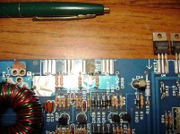
The leg is vertical so it's hard to see it but it connects the drain leg to the back of the board. This board now works great since the repair has been completed.
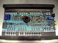
This one has similar damage and was repaired in the same way. It now works well. I also have a board of the same revision level of yours that I can help with also.
The amp powering up with one of the FETs getting hot either has a floating leg or flux is causing conduction between the legs on that FET that's getting hot.
The amp powering up with one of the FETs getting hot either has a floating leg or flux is causing conduction between the legs on that FET that's getting hot.
Attachments
I looked at the photo of Q55. It's a counterfeit Z44. Get 10 genuine Z44's from a reputable supplier and odds are things will start working well.
Even with Q55 (Z44) removed, it will not power on.. Draws lots of current (up to 10A, where I stopped), but never "powers on". Something on the board is making noise, but with Q55 disconnected- I do not detect anything getting hot.
Rail voltage never goes above +/- 3V.
My board is REV C.
Rail voltage never goes above +/- 3V.
My board is REV C.
FWIW, I bought the last batch of Z44's on Ebay from "miamielectronics". Still trying to find where I got the first set from.
Did the amp ever power up with the FETs that are still in the amp?
Never buy semiconductors from ebay.
If you have a current limiter, power up the amp and twist the transformer to see if the current draw changes. It could have an intermittently shorted winding.
Did you check the output transistors and drivers?
Never buy semiconductors from ebay.
If you have a current limiter, power up the amp and twist the transformer to see if the current draw changes. It could have an intermittently shorted winding.
Did you check the output transistors and drivers?
Up until now, I have had good results on Ebay. I used to buy parts from Digikey/Newark, etc. but they seem to have no problem charging $15 to put a few transistors in an envelope and mail it out.
Why do ye think Q55 is counterfeit? Something in the photo (I'd like to understand/learn)? Obviously, I can order more parts but have a pile of parts already that I did not really need.
I put the power on, checked and confirmed 13V. With my meter monitoring the 13V, I set the current limit to 5A, and applied power to the turn on lead. Voltage dropped to like 7V. Even when I turn up the amperage, it stays at 7V. The "noise" I am hearing seems to be the supply (Lambda LK351-FM) when it is under load.
With power applied, I twisted the transformer, and saw no change.
After a min or so, I checked for hot components, and (with Q55 still disconnected) the rest of the Z44's in the power supply were getting warm. Nothing else was.
I have checked the output transistors with OHM meter, and don't see anything indicating a bad component. Without the schematic, I can see that of the 10 transistors for each channel, 2 of them are clearly different configuration (same part number). Not sure which component is the driver.
Is there a way to isolate the power side from the amplifier?
Just remove the oddball FET.
Many get lucky (they think) on ebay because they don't push the components to the limit. There have been many instances where doing nothing but buying parts from an authorized distributor was all that was needed. That said, I don't think that that's the problem if the remaining older FETs in this amp ever worked and none are showing as shorted.
Remove the rectifiers to separate the audio section.
There are pre-drivers standing on the board in front of the outputs.
CR8,9,10,11 removed- there is no current draw. So it looks like I have a problem in the audio section.
If you reinstall the rectifiers and use current limiting, you can measure the voltage across the emitter resistors to see where the problem is. The voltage will be very low (millivolts) but you should be able to read something with a multimeter.
ah ha!
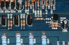
R65 had 175mV, pulled Q36. Tested again. LED power light came on, but all of the resistors on the right channel are 0V, most of the left are at least 50mV. Still seemed to be pulling a lot of current so I pulled Q35, 37, and 38.. Power draw seemed to stabilize, but that cooked R63 (assuming because only half the amplifier was working). Pulled Q28-31 to disable the entire channel.
Music now plays on the other channel!
So, I guess I need to pick up some 2N6490's. Should I replace the corresponding 2N6487's? Also need a new R63- but it is too burnt to see what it was.. Do you happen to know the value?
Based on the advice here, I should also order some new Z44's from a reputable source? Any reason to replace anything else in there to match the new stuff?
Thanks.
On my 2150 I had to find subs for the output stage, because I believe the original devices were NLA. I don't recommend mixing original and replacement transistors in output circuits, I just find a suitable sub based on HFE and current rating and go with that. If you like I can look at it when I get home and tell you which ones I wound up with.
On my 2150 I had to find subs for the output stage, because I believe the original devices were NLA. I don't recommend mixing original and replacement transistors in output circuits, I just find a suitable sub based on HFE and current rating and go with that. If you like I can look at it when I get home and tell you which ones I wound up with.
I took a quick look before, and Digikey had a 2N6490G, is that not a good sub? But, yeah- I'd be interested in what worked for you.
The "G" is a lead-free indication
https://www.mouser.com/datasheet/2/308/2N6487-D-40449.pdf
Under "Marking Diagram"
https://www.mouser.com/datasheet/2/308/2N6487-D-40449.pdf
Under "Marking Diagram"
The 2N6488 and the 2N6491 are generally what's used.
If you're going to have to replace the emitter resistor, you need to at least replace all in that half of the channel. They are essentially in parallel. Order the ceramic coated resistors (dull gray or green coating). If you order paint coated ones, they often flame up when they fail. I prefer the dale resistors (LVR03R1000FB12 these are 0.1 ohm, you'd have to order the right value if you'd use them) but they look completely different and are more expensive so most people won't use them.
If you're going to have to replace the emitter resistor, you need to at least replace all in that half of the channel. They are essentially in parallel. Order the ceramic coated resistors (dull gray or green coating). If you order paint coated ones, they often flame up when they fail. I prefer the dale resistors (LVR03R1000FB12 these are 0.1 ohm, you'd have to order the right value if you'd use them) but they look completely different and are more expensive so most people won't use them.
2N6488/6491 are better replacements? Any reasoning for that? Still not sure if I need to replace all 10 transistors? or just the ones that are bad?
Do I need to replace the emitter resistors? they all look Ok (no discoloration, etc.)
Anyone know the value of R63? I want to order that too...
Again, Thank you all for your help!
Do I need to replace the emitter resistors? they all look Ok (no discoloration, etc.)
Anyone know the value of R63? I want to order that too...
Again, Thank you all for your help!
My mistake. The emitters end at R64 in the amp photos I have (2150M). Check them to confirm that all are within tolerance.
See attached.
The 88/91 are the same but higher voltage. The 87/90 aren't as widely available (or weren't when I was buying them). The 88/91 are also more useful if you buy extras to have on hand.
At the very least, you have to replace all outputs (4+4 configuration - one per emitter resistor) that were in parallel with the failed transistor. If the channel failed due to an external fault (not a random failure), all of the outputs in that channel were pushed to the limit and should be replaced. The transistors are dirt cheap.
Attachments
- Home
- General Interest
- Car Audio
- PPI 2150 died.. :(