I don't meant Chris at all, I was just reflex to another poster who asked OP if he knew how much NFB it has, a better question would be to ask the resistor value, if not, I presume the poster knows better, that is. Don't get carry away and I don't quote him.
There is transformer model post in spice model page if you need it, but don't how accurate it is, it does include leakage inductance (in K factor), which only make a difference in roll-off frequency.
*=========================================================
.SUBCKT Ham1608A P1 Sg1 B Sg2 P2 O16 O8 O4 Com
* Push Pull transformer, with Ultralinear taps at 40%
* 8000 to 16 ohms, 3db 15 to 60000 hz
* speaker taps at 8 and 4 ohms
* Hammond 1608A
* 10 Watts
* model generated by TransformerModels.xls 2020 Feb 25
*
LP1 1 Sg1 3.91117778619697
LS1 2 B 1.73830123830977
LS2 3 Sg2 1.73830123830977
LP2 4 P2 3.91117778619697
LA1 O8 5 0.00750745724556676
LA2 O4 6 0.00375372862278338
LA3 Com 7 0.0218783337239668
KALL LP1 LS1 LS2 LP2 LA1 LA2 LA3 0.998434750532354
RP1 P1 1 64.53
RP2 Sg1 2 32.27
RP3 B 3 32.27
RP4 Sg2 4 64.53
RS1 O16 5 0.1
RS2 O8 6 0.1
RS3 O4 7 0.3
.ENDS Ham1608A
I don't meant Chris at all, I was just reflex to another poster who asked OP if he knew how much NFB it has, a better question would be to ask the resistor value
That was me who asked this question. Op did not know that. Did you notice that I gave him further instructions/information ?
Before my comments, twice were suggested to find out if GNFB was the reason for instability, but with no response.
In the end I came to the conclusion that he was only interested in changing capacitors.
He is interested to replace coupling cap first before you ask him about Gnfb. You can ask him here again, but let me ask if he played with resistor value.
Dr Freeman,
What value of resistor is used in negative feedback? Do you use different values and does breathing of speaker cone stop apart from 0.47u coupling cap?
Dr Freeman,
What value of resistor is used in negative feedback? Do you use different values and does breathing of speaker cone stop apart from 0.47u coupling cap?
Not sure about the model often they calculate the primary inductance based upon the the frequency response quoted which is quite often at full power. This gives a much lower value. My experience is that is better to use the primary inductance off the data sheet. The Hammond's usually have their first pole at 5Hz.
I stand corrected that model looks good the primary inductance is 3.9/(.3*.3) = 43H which is in the right area. I will take a look over the weekend.
Last edited:
So, let's clarify a few things:
This is my first tube power amp (not my first amp ever) and in fact I first made a prototype to evaluate any problems (which promptly arrived).
From the beginning I was advised to act on the caps, and as a novice, I did just that. I tried all possible combinations and evaluated their effects, but at the same time I was suggested to check GNFB but I was still struggling with caps. In the end a solution or pseudo solution was found and the amp "seems" stable and sounds, to me, beautifully and this already heartens me a lot. Furthermore, it does not seem to me a heresy that a novice like me does not know the amount of GNFB of a project found on the web, and if anyone thinks so ........patience, I sleep the same at night.
Having clarified this, and with a semi-solution already found, we can proceed with the verification of the GNFB, or other ways, assuming that it can be done without the probably necessary instrumentation. In this regard, I would like to strongly thank baudouin0 and Koonw for all the effort they are putting into it.
He is interested to replace coupling cap first before you ask him about Gnfb. You can ask him here again, but let me ask if he played with resistor value.
Dr Freeman,
What value of resistor is used in negative feedback? Do you use different values and does breathing of speaker cone stop apart from 0.47u coupling cap?
Exactly
No, I would not do any damage, I don't know with what values. There is now 1K as a schematic.
... is somewhere on the learning curve, has minimal instrumentation, and has not yet developed a working mental model. This is how we all are when approaching a new interest - it's the learning part that keeps us interested.
I think part of the problem is that we've become too used to being able to achieve a useful level of knowledge in most things we do, without sweating for it.
Just look at some of those deceptively simple schematics from the glory days, a synergy of theoretical and engineering solutions, penned by unnamed gurus, with dozens of years of experience, rendered readable by equally unappreciated technical drawers.
Part of the struggle is finding the right level, and accepting that that is sufficient to create an incomplete working model.
I think this is one of those 'deceptively simple schematics' a paraphase splitter but joined at the hip. Cannot quite see why is does what it does.
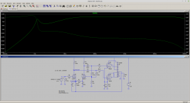
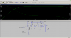
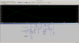
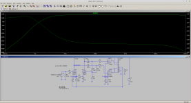
Closed loop frequency response with change.
Hi, I run an LTSpice simulation and found the results are exactly like yours, but don`t You found R7 must be tweaked to get perfect PI balance?
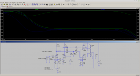
To understand what C1 is doing the plot below shows the gain from the AC source in the FB path to the plate of each half of the 12AX7. At audio frequencies the C1 acts as a short and the gain is determined by the R12 and R2. However at about 1.5Hz C1 increases the impedance and the gain starts to go up.
This has the affect of placing a zero at 1.5Hz. This can be used to cancel one of the poles of the feedback path. This has the effect of shifting one of the poles (transformer or C2/C3 which were very similar) to a much lower frequency so that in effect we now have only one dominate pole in the system.
What seems to look very simple is actually rather clever.

Please be wary of these models. They have numbers and squiggly lines, so they look like they have a solid basis in reality. They work fine as long as the model is sufficiently robust, but any model that is based on the output transformer being a fixed inductance is fatally flawed for our purposes. Changes of actual primary inductance by an order of magnitude over its working dynamic range is ordinary (for transformers designed for no standing mag field: push-pull).
I'll say it one more time, and then shut up: you need a single dominant high-pass filter in the forward path. It can't involve the OPT's inductance because that varies with signal level. It shouldn't involve any bypass capacitors because those have response shelves so aren't monotonic, therefore too tricky to predict without measuring capability. All these things should be pushed down in frequency as much as practical.
Use as much static OPT inductance as possible and as much bypass capacitance as possible. Decent bypass caps are almost free these days.
Set a high pass pole (actually a zero, but) with an RC coupling. I recommend the coupling caps to the final valves' grids. This is where the amplifier clips, so will benefit most from the smallest time constant by reduced recovery time. Make this pole several octaves (at least) above the others.
All good fortune,
Chris
Last edited:
Read the simulation results Chris they are quite interesting rather than just dismissing. I am fully aware of limitations that can occur particularly in the transformer. Terms like 'fatally flawed' express an opinion rather than science and appear a lot on diyaudio. We are only looking at small signal here so the change in primary inductance should not be significant. The instability starts in the small signal level. My understanding of this parameter is that it can be difficult to measure - however its value should only change when the core begins to saturate. This may well explain why the amplitude becomes limited. The designer of this amp came up with a better solution than just two poles. He was using pole-zero cancellation in the loop. I spent a couple of hours looking at this. I've also measured transformers and built into models so I can get the NFB of a real amp correct. And yes the simulation and the amp do match if you put time and effort in.
And a high pass filter is not a zero, its a real pole plus a zero.
And a high pass filter is not a zero, its a real pole plus a zero.
Last edited:
So a quick solution is to limit the reactance of C1 to a specific value 200 (say shunt C1 with 200 ohms). There are just too many areas but this is a new discovery, well done baud!
Happy Sunday everyone
tried the combination 0.1uF and 570uF and the result is excellent 🙂 (thanks baudouin0). The cone is freeze and the DMM display reads an excellent and comforting 5 mV Max. Also, I don't know if it is suggestion but, I seem to note that the already excellent bass is further improved in terms of punch, frequency response and rhythm. It's possible?
tried the combination 0.1uF and 570uF and the result is excellent 🙂 (thanks baudouin0). The cone is freeze and the DMM display reads an excellent and comforting 5 mV Max. Also, I don't know if it is suggestion but, I seem to note that the already excellent bass is further improved in terms of punch, frequency response and rhythm. It's possible?
Happy Sunday. The 200R will affect the plate voltages of the paraphase stage. The correct solution is exactly what you have done. We all missed the cleaver way the designer had implemented the negative feedback. Only Mr LTspice knew what was going on - Mona made the suggestion but with no explanation. The bass may be a bit more solid as the stability is now good. More likely is the phase balance of the paraphase is better at LF with the mod. I certainly learnt something.
Last edited:
- Home
- Amplifiers
- Tubes / Valves
- PP EL84 Problem (HELP)
