This isn't any Earthquake Shake mega-amp. 0.02u puts the corner at the edge of the audio band, and masks the variable response of the output transformer. Also 0.02u is cheaper than 0.1u or 0.32u.
Since there is NFB you do not have to put the inner poles at 20Hz to get 20Hz overall response. You should cover the power in the signal. Very-very few recordings have power below 50Hz. (The few that do will challenge any two-6V6 amp.) Note that guitar amps aiming for 82Hz sometimes shave the driver pole near 160Hz, because a little NFB will extend the response and the short time constant recovers from clipping quicker and less ugly.
Since there is NFB you do not have to put the inner poles at 20Hz to get 20Hz overall response. You should cover the power in the signal. Very-very few recordings have power below 50Hz. (The few that do will challenge any two-6V6 amp.) Note that guitar amps aiming for 82Hz sometimes shave the driver pole near 160Hz, because a little NFB will extend the response and the short time constant recovers from clipping quicker and less ugly.
Try reducing the negative feedback amount. There could be LF instability caused by too much of that.
PRR I agree that a small cap will also work. The worse case is the .1uF currently where the gain at 2Hz must be big. Making the cap bigger will also reduce the gain at LF too. The danger of making the cap small its that at 20Hz the driver may start to clip before the output stage causing distortion. The best place to reduce the LF is a coupling cap at the input outside the FB loop. I would also see if that 100uF at the input of the FB loop has an effect too that's another pole. I would try making that cap (on the input cathode to ground) say 470uF.
Last edited:
I've tried 560u in place to 100u, with 0.1u coupling cap but nothing effect.
I will try 0.02u and choose 0.47u or 0.02u.
I will try 0.02u and choose 0.47u or 0.02u.
Remember that your goal for loop stability is to establish a single dominant pole (actually a "zero", but), and that this is a brute force solution. You want to set the open loop low frequency response to look like a single pole high pass filter. Any elements of the low frequency response that are significantly different from this are troublesome if the forward gain is still above unity.
All of the RC pairs in the forward path contribute something to the low frequency response, as does the RL pair at the output transformer. (No RC pair in the feedback path should ever be allowed). One of these pairs needs to be chosen as dominant, that is, to be far enough away from the others (higher in frequency) as to dominate the low frequency response enough that it looks safely enough like a single pole high pass filter.
So, which of the existing poles to make dominant? The cheapest solution is the output transformer's primary inductance shunting the output valve's source Z, but this varies dramatically with signal level, and in the wrong direction. Cathode bypass caps across their resistors have associated zeros (actually poles, but) so only cause grief.
The remaining choice is a coupling cap location. I vote for the coupling caps feeding the output valve grids; others prefer someplace further upstream.
But folk remedies involving hit and miss juggling of bypass cap values is rearranging deck chairs. Ya gotta bite the bullet and set a dominant pole. And make sure there isn't an alternative feedback path through the power supply. Here again, brute force.
YOS,
Chris
Hi Chris Hornbeck thank you for support.
The 0.32u in coupling caps works fine and I think 0.47u better.
I still have to try 0.02u but now I don't have them.
Theoretically which of the two is better in your opinion (assuming 0.02u works)?
The 0.32u in coupling caps works fine and I think 0.47u better.
I still have to try 0.02u but now I don't have them.
Theoretically which of the two is better in your opinion (assuming 0.02u works)?
PRR has already (twice) pointed in the right direction. If that's too radical for audiophile sensibilities, .033uF is probably small enough if DC current in the primary is reasonably balanced.
All good fortune,
Chris
All good fortune,
Chris
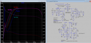
Here are snapshot of effect of cathode coupling capacitor from 47u to 200u where other capacitor values no change. Noted the phase shift (need more comment here). I also add a AC balance control as the two phase splitter level is about 2 dbs difference even after 15 Nfb being applied. The value of Nfb resistor will cause the bottom response and also phase shift to shift the same way as if cathode cap is being varied. If there is a phase shift then oscillation is likely too.
Attachments
Last edited:
I've tried 560u in place to 100u, with 0.1u coupling cap but nothing effect.
I will try 0.02u and choose 0.47u or 0.02u.
Your woofer breathing has nothing to do with coupling cap values. They will not pass 1hz. The transformer itself will not pass 1hz. You have a circuit grounding/speaker/grounding/FB line and PS filtering anomaly. How about a photo of your prototype layout?
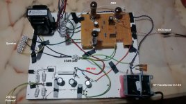
You don't have a fully neutralized common ground system for the PS or signal lines because your "ground" is from the rectifiers and you also attempt to create a ground to the heaters via the tangent resistors to that transformer so you are mixing two transformer outputs and tying them together at your star ground. I also don't see the FB resistor and cap, are they hidden underneath? With this breadboarding circuit it's not unusual to have the kind of filtering problem you are getting. It's all in the grounding circuit and filtering.
Here are snapshot of effect of cathode coupling capacitor from 47u to 200u where other capacitor values no change. Noted the phase shift (need more comment here). I also add a AC balance control as the two phase splitter level is about 2 dbs difference even after 15 Nfb being applied. The value of Nfb resistor will cause the bottom response and also phase shift to shift the same way as if cathode cap is being varied. If there is a phase shift then oscillation is likely too.
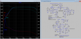
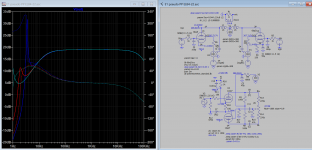
That shows the problem up nicely I guess you took the transformer values off the Hammond web site. I don't think Dr F tried increasing the output cathode caps. Could you also try .47uF coupling caps and PPR suggesting of .033uF. Mona suggested the output cathode caps.
The bottom line is that it's not a surprise to see some PS irregularities at the speaker common gnd. coming in from the star gnd. and not be true "0". There could be a small variable DC level created by the heaters if they cycle in temperature slowly creating a variable voltage drop through the resistors that create the virtual ground going to the star ground. .... just a speculation...
Last edited:
Yes the FB resistor and cap are hidden under the board.You don't have a fully neutralized common ground system for the PS or signal lines because your "ground" is from the rectifiers and you also attempt to create a ground to the heaters via the tangent resistors to that transformer so you are mixing two transformer outputs and tying them together at your star ground. I also don't see the FB resistor and cap, are they hidden underneath? With this breadboarding circuit it's not unusual to have the kind of filtering problem you are getting. It's all in the grounding circuit and filtering.
Therefore you think that the problem is due to transformers that do not have central sockets?
Unfortunately I only have these for tests. Obviously the final construction will have transformers with cental pin as schematic.
Last edited by a moderator:
That shows the problem up nicely I guess you took the transformer values off the Hammond web site. I don't think Dr F tried increasing the output cathode caps. Could you also try .47uF coupling caps and PPR suggesting of .033uF. Mona suggested the output cathode caps.
Hammond 1608a bottom response is down to 30Hz, the sim transformer has primary 60H should be well covered for the bottom range. Here are plots you requested.
Attachments
Therefore you think that the problem is due to transformers that do not have central sockets?
The heater circuit can stay isolated and work OK, so you can test that part by lifting the resistors off the ground line. Did you ever test it that way but found some hum so you added the virtual ground? ... You also have to consider that the input signal line has a common line back to the source unit, preamp, or whatever, and will be puting that device's ground system into the amp's ground system so any weirdness will work its way backward to the source, and may create noise or hum. So it's important to have a conventional ground system in place that you don't have yet. Normally you would ground the input line to troubleshoot the amp without input signal, but if your trouble is in the ground system it could create other symptoms that just add another layer of trouble.
- Home
- Amplifiers
- Tubes / Valves
- PP EL84 Problem (HELP)