Yes I measure, Emitter shows typical .7v voltage drop across a transistor junction.
15v in 14.3v out.
Cheers / Chris
15v in 14.3v out.
Cheers / Chris
The simulation, page 6, should show that well enough or is morbid curiosity getting the better? 😀...I almost (but not quite!) want to put a 'scope on this to see what abomination is provoked on the supply pins depending on signal and load.....
There should be very little power dissipation in the transistors, whatever value resistors are used. If they get warm, that could be a symptom of oscillation.
See attached diagram showing a single op amp.
Cheers / Chris
Attached diagram does not show transistors, in any case it does not correspond to any transistor symbol I have ever seen...
And, how do you get more than 7mA since the quiscent current of your OPamp is about 7mA pretty much from minimum to maximum operating voltage?
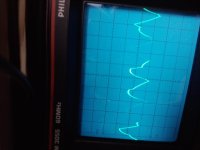
Image one shows my Philips scope with V+ measurement at .5mv ac, and 0.5ms prior to transistor. .. signal that would otherwise be applied to op amp pin.
Attachments
Last edited:
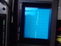
Image two shows my Philips scope with V+ measurement at .5mv ac and 0.5ms exiting transistor.
Attachments
Last edited:
15/2400 = 6.25ma , 12/2400 = 5ma Listening tests show 5-6ma as ideal. I have tried to 10ma, and no thermal runaway, but gets quite warm.
Cheers / Chris
Chris, you seem under the impression here that the supply voltage appears across the 2K4 resistor and so "gives" 6ma base current.
Yes I measure, Emitter shows typical .7v voltage drop across a transistor junction.
15v in 14.3v out.
Cheers / Chris
And here you say you have measured it (hooray !) and that the emitter shows a 0.7 volt drop, although you don't actually say which junction E-C or E-B.
I would now suggest you measure the base current directly with a DVM and then confirm that by measuring volt drop across the resistor and calculating to ensure agreement in the results.
Now try this. Forget AC measurements and do a DC test by loading the opamp with (say) 600 ohm and apply an input signal such that the opamp supplies its rated max current.
Now repeat the tests on the 2K4 resistor.
You will find you get nothing approacing 6ma in the 2K4.
... or is morbid curiosity getting the better? 😀
It is with me 😉 This evening I'll throw an OP27 onto a breadboard with a +15/-15V lab supply, feed it a 1 MHz 1Vpk signal, loaded with 680Ohm and get some scope images. With and without transistors. You know, like a controlled test setup.
Edit: No, I will not listen to it - my subjective babble is not as accurate as scope images that every engineer wil perceive the same way.
Magic Box Thanks, I look forward to results, and thanks Mooly for instruction with current across resistor.
Cheers / Chris
Cheers / Chris
Last edited:
From datasheets I note PSRR for an op27 at 1Mhz is -20db V- and -16db V+
vs AD825 somewhat better -30db V- and -35db V+ at 1 Mhz🙂
Cheers / Chris
vs AD825 somewhat better -30db V- and -35db V+ at 1 Mhz🙂
Cheers / Chris
There is no point of measuring voltages to verify Ohms Law.
The law it is still in effect and will degrade the power on supply pins (compared with a straight wire connection) - voltage drop will be there. The only way that can work is with a storage capacitor at each pin of the OpAmp (like when we use any resitor series on power rails).
Sure, the OpAmp will diminish that (not cancel) variation due to PSRR, but that will take a toll from total gain available. The OpAmp will sound worse because of that.
Last edited:
From datasheets I note PSRR for an op27 at 1Mhz is -20db V- and -16db V+
vs AD825 somewhat better -30db V- and -35db V+ at 1 Mhz🙂
Cheers / Chris
It is very dangerous to extract hard numbers like this from data sheet graphs.
I am looking at page 11 of
http://web.mit.edu/6.301/www/OP27c.pdf
PSRR v frequency is a tiny graph from CHARACTERISATION of samples of the device. It is not tested or measured or guaranteed in production but probably is reasonable since those PMI engineers know their process and designs. A clue is the nice straight slope of the fall, indicating some dominant pole roll off.
But picking off precise dB values is mostly guesswork. A circuit to measure this parameter at high frequency requires precise layout and decoupling to be repeatable (hence meaningful).
Can I be permitted to put in a few hypothetical numbers to add to the few known numbers we have been given?
supply = 15V000
output = 14V300
Vce= 700mVce
Rcb = 2k4
Let's guess that ~1% of the total 6mA of current demand flows through the CB resistor, i.e. 60uA.
The voltage drop across the resistor is ~60uA*2k4 ~ 144mVcb
Vbe ~ 700mVce - 144mVcb ~ 556mVbe
So we have:
Vbe=556m
Vce=700m
Ib=60u
Ic=6m
Ie=5940u
The approximate hFE is 5940/60 =99
The transistor is not saturated. The guesswork can be iterated towards a more correct value using the available datasheet information.
I don't see a problem in analysing what the transistor Vdrop is.
I don't see a problem in analysing the current demand of the opamp. eg. let's assume the output is ClassAB and biased to 1mA.
The voltage amp stage demand will be 5mA. The total variation in opamp demand will be ~ 5mA to 40mA.
Apply that range of demand to the transistor and see what the Vdrop of the transistor is.
If you want you can convert the Vdrop at each current into an effective resistance.
Let's see a plot of effective resistance vs current demand. The simulator should make this plot easy to see.
Hi AndrewLet's see a plot of effective resistance vs current demand. The simulator should make this plot easy to see.
I think it would be more interesting to look at a plot of impedance vs frequency. This is likely to be rising above about 1Mhz due to the falling current gain of the transistors.
So instead of the common practice of having small bypass caps close to the chip, there is effectively some inductance added in series with the power supply rails (probably resonating with stray/parasitic capacitances higher up).
Chris did mention that under some conditions the transistors get warm, which sounds to me like something is oscillating and drawing extra current.
Cheers - Godfrey
I don't think think the engineer-minded people are in disagreement on how to measure/simulate/calculate on this circuit, so I'm sort of surprised why we go about the obvious. Defying persistent belief perhaps?
I see Andrew has presented the calculation (see post 153) which I was about to give. As the BJT is not (quite) in collector saturation, we have simply a non-linear resistance divider (c.f. capacitance multiplier). As I said many posts ago, the effective AC resistance is around 26/Ie + Rb/beta.
The BKT should definitely not get warm, as it is only dissipating about 4mW! If it is oscillating, which is possible, then the op-amp is likely to be significantly disturbed by this - the sound will change but not for the better.
The opamp quiescent current may change a bit with supply voltage, but any large change probably means it is being stressed by under or over supply voltage. I don't quite know how to put this politely, but the more Chris says about his circuit the more convinced I become that he doesn't understand it.
IMO circuit board layout is as important as the circuit design itself. One can find the ideal design when simulating but when implementation in the real world, the circuit may not behave as simulated. For example bypass caps next to the op-amp might not work well without a ground plane and caps are not ideal over frequency. Even when using a solid tantalum cap I always parallel a good ceramic RF cap so the higher frequencies are also by-passed. There are always assumptions made when simulating a design. Validating the simulation by building a real world model (in the case of audio gear also listening to the real world model) avoids making the word assume into that acronym we all fear.
Don
Don
I'd think it's the opamp oscillating at some ultrasonic or MHz+ range frequency, and the extra current it pulls then heats up the transistors. With both a nonlinear resistance and an effective inductance in series with each power pin, an oscillating opamp in a "non-oscillator" circuit would not be surprising, it's even almost expected.I see Andrew has presented the calculation (see post 153) which I was about to give. As the BJT is not (quite) in collector saturation, we have simply a non-linear resistance divider (c.f. capacitance multiplier). As I said many posts ago, the effective AC resistance is around 26/Ie + Rb/beta.
The BKT should definitely not get warm, as it is only dissipating about 4mW! If it is oscillating, which is possible, then the op-amp is likely to be significantly disturbed by this - the sound will change but not for the better.
This will definitely change the sound and arguably deteriorates it from the original, but whether the sound is "better" is in the ear of the beholder.
Is it possible these additional transistors actually form an oscillator in combination with the capacitance at the emitter... it would be in the hf and uhf region I imagine.
I have in my mind a very strange problem that caused a lot of commercial gear to fail EMC tests. The cause was a single transistor reset generator oscillating. If we have inductance in the collector side and capacitance on the emitter we are half way to a colpitts oscillator.
I have in my mind a very strange problem that caused a lot of commercial gear to fail EMC tests. The cause was a single transistor reset generator oscillating. If we have inductance in the collector side and capacitance on the emitter we are half way to a colpitts oscillator.
I have the feeling that powering OpAmps this way will be way more beneficial if the OpAmp is biased into class A itself. Forcing current into an OpAmp working in class B operations is just the equivalent of adding great amount of capacitance on the power rails- it does the same thing essentially by implying current rush to the chip. As far as I know, current rush/high rail capacitance are not advised to Class B operating chips.
This is by my understanding.
This is by my understanding.
- Status
- Not open for further replies.
- Home
- Amplifiers
- Solid State
- Powering Opamps???