If that schematic is correct, analysis starts off being simple:
There is (15v-Vbe) / 2K2 base current, ~= 6mA
Op-amps generally draw a constant current apart from the load current which is signal/load dependent. Data sheet says ~=6mA
So with Ib = Ic = 6mA, transistor is hard saturated. Thus we have 0.1v - 0.2v drop on the supply lines, which will change according to the load current. this modulation will effect the output by 1/PSRR.
A waste of time, AFAICS.
And no, I an NOT going to breadboard it and listen, just as I won't for any number of crackpot ideas in a similar vein.
If you want to get the attention of engineers and enthusiasts, at least do a bit of homework and learn some basic (high-school!) engineering.
Might I still persuade you to breadboard an opamp with these bypass transistors and listen? Then you could have heard that you have a little error in your analysis. Ib is as much as Iq / beta. Ib * Rb determines the actual voltage at the emitter, is Vpos - 0.65 - (Iq/Beta)*Rb.
😉 Ofcourse you already knew this..
😉 Ofcourse you already knew this..
Last edited:
Might I still persuade you to breadboard an opamp with these bypass transistors and listen? Then you could have heard that you have a little error in your analysis. Ib is as much as Iq / beta. Ib * Rb determines the actual voltage at the emitter, is Vpos - 0.65 - (Iq/Beta)*Rb.
😉 Ofcourse you already knew this..
That does mean the transistor isn't actually saturated as Vce will be about 0.7v, just above saturation voltage I expect.
Nonsense!
Ib is forced. Ohms law.
"Then you could have heard that you have a little error in your analysis"
HTF does that work? I would HEAR an error in circuit analysis ?
Ib is forced. Ohms law.
"Then you could have heard that you have a little error in your analysis"
HTF does that work? I would HEAR an error in circuit analysis ?
That's about right, it's a little more. The simulation shows a drop of about 1V across the emitter/collector. If anything, it's a load driven supply modulation booster as seen from the opamp powerpin. This is also shown in the simulation; the voltage swing at the emitter is larger than the voltage swing on the power rail itself.
That's about right, it's a little more. The simulation shows a drop of about 1V across the emitter/collector. If anything, it's a load driven supply modulation booster as seen from the opamp powerpin. This is also shown in the simulation; the voltage swing at the emitter is larger than the voltage swing on the power rail itself.
The emitter IS the power rail!
We are not talking about the same schematic.
Nonsense!
Ib is forced. Ohms law.
Yes, Ohm's law. It's just that now you have to apply it in a different direction. You are assuming the emitter sits at 0V (your 15V - Vbe across the resistor). But the emitter doesn't sit at 0V. It sits somewhere between 0V and 15V. You won't know at what voltage unless you start calculating from the opamp's idle current. It's this current that dictates, together with the transistor's hFE what the ultimate voltage drop is going to be.
The emitter IS the power rail!
We are not talking about the same schematic.
LOL you're talking about that last schematic with the base resistors connected to ground, emitters to power rail and collectors to opamp? Then yes, you're right; I was talking about the original schematic.
Indeed 😱 that was a waste of time!
However, using the OP cct in the first post, it is entirely a question of the transistor gain.
To a first order, the OA supply line is a constant current, so a simple model is the transistor with a 6ma source in its emitter.
Where it all goes depends on Hfe. i.e. it is ill defined.
So what next?
However, using the OP cct in the first post, it is entirely a question of the transistor gain.
To a first order, the OA supply line is a constant current, so a simple model is the transistor with a 6ma source in its emitter.
Where it all goes depends on Hfe. i.e. it is ill defined.
So what next?
Now you go solder extra transistors and resistors all over your sound system,So what next?
and convince yourself it sounds better (otherwise you have to unsolder the whole mess all over again).
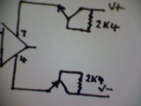
In an op amp circuit there is no defined ground connection, you have therefore drawn the schematic wrongly. The resistor for each polarity connects between the collector and base
the emitter connects to the op amp power supply for each polarity. I have used this with BC846 and BC856 transistors, suiting surface mount application, and 0603 2k4 resistors
see my blog for construction help: opamp - opamp construction. If using TO92 then BC547 and BC556. recommend Voltage supply 12- 15v dual polarity, max voltage 17.5.
See attached diagram showing a single op amp. Next find your soldering iron and a op amp installed in an audio circuit,like a CD player or any other audio circuit- this is after all the DIY Audio Forum, modify the way it connects its power rails as per the diagram.
Cheers / Chris
Attachments
Last edited:
OK, fine. What you posted now is the same circuit as in post 1, but how do you figure out the base current is 6mA?
...It was then a matter of tailoring the base current to suit. Much experimentation found 6ma to be ideal...
...a resistor at 6ma bias to each polarities base...
Last edited:
15/2400 = 6.25ma , 12/2400 = 5ma Listening tests show 5-6ma as ideal. I have tried to 10ma, and no thermal runaway, but gets quite warm.
Cheers / Chris
Cheers / Chris
Yes, 15 Volts divided by 2400 Ohms = about 6mA.
However in your circuit there is not anywhere near 15V across the resistor, so the current won't be anywhere near 6mA, unless the circuit you're using is different to the drawing you posted.
However in your circuit there is not anywhere near 15V across the resistor, so the current won't be anywhere near 6mA, unless the circuit you're using is different to the drawing you posted.
What gets warm: the transistors, the resistors, or the opamp?...I have tried to 10ma, and no thermal runaway, but gets quite warm.
Last edited:
Which asks the question how current is determined or defined in such a connection lacking ground. The op amp itself may pull, request, demand current. From my use with this circuit it expends current through the emitter to the op amp relative power supply pin.
Cheers / Chris
Cheers / Chris
Which asks the question how current is determined or defined in such a connection lacking ground. The op amp itself may pull, request, demand current. From my use with this circuit it expends current through the emitter to the op amp relative power supply pin.
Cheers / Chris
Here we are again. That is meaningless. Gobblydegook.
So is "ground". Ohm and Kirchoff have worked well for us for many years.
I almost (but not quite!) want to put a 'scope on this to see what abomination is provoked on the supply pins depending on signal and load.
Chris, have you ever MEASURED anything? Or is it all "chuck in components and listen to how it sounds"?
- Status
- Not open for further replies.
- Home
- Amplifiers
- Solid State
- Powering Opamps???