The difficulty of adding a capacitor in an op amp circuit is that ground is not defined ie there are probably 40% non inverting vs 60% inverting, population out there some using Pin 2 some using Pin 3, and then there is ground lift in some of that population, so what is an answer- given that an opposite polarity is available in terms of the other voltage rail a capacitance added to the base of each transistor as a cap multiplier might ... and a big might .. er ...function by instead of ground by connecting to this opposite polarity rail.... let me connect such a circuit up and report back.
Cheers / Chris
Cheers / Chris
First of, an emitter follower is a three port device, and its an amplifier, your circuit is niether.
Aren't we touchy. No one is looking for an argument, just a reasonable explanation for a subjective opinion. And if you post, you will get replies that dont agree with you (no matter what you post). A lot of people are here to learn about electronics, and subjective opinions teach nothing, but can lead to objective results. Sorry if we dont take your opinion as the correct one but these pages are full of subjective impressions that make very little sense and have zero proof. Your only one step removed from the "felt pen on the edge of my CD makes it sound better" group.
I guess you are asking me what the right theory is. if you care to stop looking for an argument in posts you will have read i do not have a theory!End of. As i like a good argument1 you are not my chosen to argue with in any constructive way. In any way for that matter . also the post was not in reply to you in any way. Now if you would like to be littel me in any way i can tell you now you will be wasting any time and effort you expend . Now back to the intresting thread hey. Oh by the way im sorry for putting a smudge on this great thread . Df had the option to keep this private so he is half to blame too.
Aren't we touchy. No one is looking for an argument, just a reasonable explanation for a subjective opinion. And if you post, you will get replies that dont agree with you (no matter what you post). A lot of people are here to learn about electronics, and subjective opinions teach nothing, but can lead to objective results. Sorry if we dont take your opinion as the correct one but these pages are full of subjective impressions that make very little sense and have zero proof. Your only one step removed from the "felt pen on the edge of my CD makes it sound better" group.
Why do you not simply use a Led ? An IR Led drops some 1.2V though but is a decent constant current source in itself.
MagicBox,
In my book, that would be an emitter follower and very much in line with adding a capacitor to the base as DF96 has mentioned.
Hope this helps
-Antonio
Yeah, though if Ic/hFE drops a decent voltage over the base resistor, it stops acting like an emitter follower. It still could be, though driven by an input (V+) with a high output impedance, causing the actual voltage on the base to vary with current load, which will happen when the opamp is 'working' on signals. Best to throw it in the sim, attach some scopes and see what's going on.
"The transistor monitors continuously Vdiff and adjusts its emitter voltage almost equal (less VBEO) to the input voltage by passing the according collector current through the emitter resistor RE. As a result, the output voltage follows the input voltage variations from VBEO up to V+; hence the name, emitter follower"
And the circuit proves itself with the same characteristics by improving audio performance.
Cheers / Chris
Except you forgot to quote something that is always a given, and that is 'the transistor is correctly biassed into the normal operating region'. I'll leave it to you to find out what that means.
That aside, since your signal to be followed comes from the power supply rail, then it follows the power supply rail, the very thing you do NOT want it to follow as you are trying to prevent electrical garbage from getting into the chip.
However, at some high frequency this does indeed work as a sort of cascode due to not so inconsiderable Cbe, given the transistor is near saturation for the resistor values given. This WILL actually isolate it from small amounts of HF hash, making the transistor look more like a current source in series with the power supply. It would work much better with the usual caps on the opamp side for decoupling, though, or, connected as a gyrator. In fact you could try to couple the bases through a capacitor.
Another possibility is nonlinear modulation of the substrate potential WRT inputs, but this would be chip dependent. Such a thing could in some cases provide a measure of distortion cancellation.
BTW the reason for all this discussion is that an experiment showing something works ultimately has no predictable practical application if you don't understand why it works. Without this understanding, it's just a hit and miss thing, even if there are a lot more hits than misses.
How about powering this opamp? http://i72.photobucket.com/albums/i163/miltons_stuff/PhilbrickOpAmp.jpg
If Mr Daly has experimented with this and found it works with several different types of op amps and....has the confidence to sell it then surely there must be something in it. Why don't the clever ones here who have theory coming out of their ar.. ( and there's plenty here right now arguing over it ) actually build one and post their findings ?
Then you can all decide amongst yourselves what it's called and why it works.
It seems stupid to me to go round and round in circles disputing everything when not one of you really know why it works.
We all said the earth was flat till we invented ' long haul ' boats and then found it wasn't.
We also got relief from infection from Potatoes - I wonder what the doubters were saying when that was posted on DIY Medical.com years ago ?
The feedback left by those who have bought and use them is all positive. They are neither deaf nor care for this anorak rubbish and frankly neither do I.
Slap me down all you like, I just want to know if I should give it a go myself
and hear the benefit ( or not )
Chris...how about under an LME49710 or a Burson ? 😉
How about powering this opamp? http://i72.photobucket.com/albums/i163/miltons_stuff/PhilbrickOpAmp.jpg
I'll have a go at that in a minute - I'm busy with my op amp
If Mr Daly has experimented with this and found it works with several different types of op amps and....has the confidence to sell it then surely there must be something in it.
Yea, money. There are hundreds of so called audio improvements for sale that are pure snake oil, that have the support of large numbers of people. This means nothing. For the tenth time, this circuit is not an emitter follower, and since Mr Daily believes it works because it is one (he needs to learn some electronics) his whole sales pitch is wrong.
Mr Daly has experimented with this and found it works with several different types of op amps
Far from it, he has listened to it and he thinks it sounds better, that dosnt mean it actually works.
Last edited:
and....for the 2nd time....I don't give **** what it's called
He has a soldering iron and you have a scope and calculator - who is the fool ?
I just have ears and want to make some gains from learning.
If you are all so clever why not build it - test it and then tell us how wrong it is.
Armchair warriors - this place is full of them
Music first - bollock's second
I don't know if this is possible, why can't someone SIM this and see if it's doing good/bad?
Cheers George
Cheers George
If someone took up the enormous challenge of Simming an Opamp and 2 BJTs 🙄, it would make sense to also look at the various claimed equivalents like 10-100R resistors as well.
Then, when we've all decided that none of this works but it does makes a difference somehow, we can all go back to saying black is white and aural perception is unimportant to audio etc.
To disprove a claim of aural improvement, you need to demonstrate that it does not do so. Merely assuming that disproof lies in saying it can do nothing for possibly unrelated reasons is not a very sturdy soap box IMHO.
Last edited:
It's simple enough to prove/disprove whether it makes any difference. You build one circuit with the 2 transistors added, and an identical one without them. Feed the same input signal to both (i.e. parallel the inputs), preferably using music as the signal. So, now you should have 2 identical outputs if the transistors make no difference, and different outputs if they do.
Treat these 2 outputs as one, i.e feed the 2 outputs to the input of an amplifier, preferably one with a balanced input, although an unbalanced one may be OK if the opamps are powered from an isolated supply. If there's no sound there's no difference between the 2 signals. A balance potentiometer may be needed in practice, set for a null at 1kHz before commencing music tests, due to feedback resistor tolerances affecting gains slightly. If the transistors work then I would expect to hear a signal that isn't just the original music, it should have a lot of 'extra'.
Treat these 2 outputs as one, i.e feed the 2 outputs to the input of an amplifier, preferably one with a balanced input, although an unbalanced one may be OK if the opamps are powered from an isolated supply. If there's no sound there's no difference between the 2 signals. A balance potentiometer may be needed in practice, set for a null at 1kHz before commencing music tests, due to feedback resistor tolerances affecting gains slightly. If the transistors work then I would expect to hear a signal that isn't just the original music, it should have a lot of 'extra'.
Or perhaps, a lot less!😀....it should have a lot of 'extra'.
A differential op-amp fed from the two DUTs should suffice for this purpose, but who is getting out of their armchair to breadboard it? 😉
I'll try to come up with at least a simulated version 🙂 Differential residue simulation coming up..
Ah....interesting, thanks Magic Box.
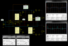
'Just a bit puzzled about IMhz shown in settings blocks but 1KHz shown on graph frequencies of the Sim. Scaling factor? Harmonic resolution?
'Not so sure I want to fudge a broader sound stage etc. that way, either. 😱
'Just a bit puzzled about IMhz shown in settings blocks but 1KHz shown on graph frequencies of the Sim. Scaling factor? Harmonic resolution?
'Not so sure I want to fudge a broader sound stage etc. that way, either. 😱
Well, decide for yourselves folks:
It looks like some people like a bit of added distortion🙂
Funnily enough I've always been persuaded that a tiny bit of the right type of distortion can add a sense of heightened presence and realism to music but I can't imagine that spike qualifies😉
The light blue trace on the lower scope containing spikes as i read it is the output of the op amp without the transistors. The Red trace resolves a sine wave... interesting at 5ma or slightly less allowing for resistor and inductor in the sim ... try 6ma by stepping PSU up to 15v
Cheers / Chris
Cheers / Chris
- Status
- Not open for further replies.
- Home
- Amplifiers
- Solid State
- Powering Opamps???