Hi Peter,
I like that solution a lot more than having new transformers wound.
Leakage is measured across a 1K0 resistor normally.
-Chris
I like that solution a lot more than having new transformers wound.
Leakage is measured across a 1K0 resistor normally.
-Chris
We used to have motor rebuilding/rewinding shops near us, but no longer.
Maybe better at winding/rewinding audio transformers, Heyboer and Pacific Transformer will also do custom winds, and Pacific will reverse engineer transformers if they don't have the specs. I've used many line number transformers from Heyboer, and have had Pacific custom make some for me for my guitar amps. I think Edcor also does custom winds, but that should be verified.
Maybe better at winding/rewinding audio transformers, Heyboer and Pacific Transformer will also do custom winds, and Pacific will reverse engineer transformers if they don't have the specs. I've used many line number transformers from Heyboer, and have had Pacific custom make some for me for my guitar amps. I think Edcor also does custom winds, but that should be verified.
When I used them in PA work I ended up replacing the op amp in the front end with a 353, on a little daughter board. Used the second op amp to add balanced inputs. Replaced the RCA jacks with 1/4” TRS. Problem solved permanently. The other alternative was to use very expensive full audio band input coupling transformers which I didn’t have the budget for in those days.
this mirrors my past experience with these...
I know that MY variac is just a variable auto transformer, not isolating. But the power transformer in the Phase Linear SHOULD be isolating. With the primary connected to the line, I'm getting 60 VAC on the secondary centre tap.
I am going to perform the following test, asap, on the transformer of my second amplifier, which is exhibiting the leakage.
If the leakage is due to inter-winding capacitance, I should measure leakage even with only one leg of the primary connected (?)
Just looking at your diagram here Peter. The interwinding capacitance on a 1.2 kVA toroid is 1.3 nF (measured). EI’s are usually lower, but can be quite high as well. You may be counfounding your leakage measurement because of the large loop back to the central ground if I’m reading your diagram correctly.
One way to simplify this would be to short the main primary wires together, short the secondary wires together, and then apply mains across the two with a 1 k resistor in series and connect your meter across the 1k resistor. Use your variac to gradually turn up the voltage. You should then get a decent leakage reading.
Attention: exercise extreme caution - mains involved.
The stray field on an EI transformer is very large compared to a toroid. You could try wrapping a copper foil GOSS band around the outside of the power try transformer - these make a very substantial difference. Check the wiring to the pots - there’s a write-up on pageS 61 to 64 on the ground loop link below that discusses this and how to minimize the loop area.
Anyway, awesome amp - I remember hearing them with the PL preamp with the joystick about 40 yrs ago. Good luck with your restoration!
Last edited:
Project for today: Leakage test (input and output windings will be shorted and the voltage across a 1k series resistor will be measured with line voltage applied between primary and secondary, as per Bonsai) ----- EXTREME CAUTION here.
I am posting on a forum dedicated to Phase Linear and stray magnetic flux was suggested as a concern. I performed the test pictured and posted this comment;
"The steel angle had no effect on the hum/buzz. The ground wire that was connected to my IEC socket ( to the capacitor common buss ) is removed. When the amp chassis is free-floating (chassis about 62 VAC to neutral) and a 10 k resistors between pins 1 and 2 on the PL14_20; the hum/buzz increases as my finger approaches the resistors. Buzz also increases as my finger got within 1/4" or so of the op/amp IC's on the PL14_20.
This effect from my finger did not happen when I alligator clipped the chassis to the wall outlet ground. I assume the capacitive effect of the amp having 62 VAC compared to my finger causes hum. But should the PL14_20 be so sensitive to capacitive influences of is there a possible (wiring) issue?"
Attachments

Yes you will get hum/buzz with the chassis floating. The chassis must only connect to the secondary 0V where the two main filter caps join and there must absolutely not be any other connection to the chassis otherwise you will have a ground loop.
Did you get a leakage reading BTW?
Did you get a leakage reading BTW?
Hi Bonsai; I did your suggested leakage test on this amp;
"short the main primary wires together, short the secondary wires together, and then apply mains across the two with a 1 k resistor in series and connect your meter across the 1k resistor. Use your variac to gradually turn up the voltage"
I measure 104 mVAC across the resistor. I will measure my other PL700 for comparison. I would be extremely curious to see results of this test on other transformers if anyone is able. Again as Bonsai has mentioned; EXTREME CAUTION
with line voltage and alligator clips!!
PS: The chassis has always been tied to the common connection bus between the filter caps, in one place only.
Looks like your transformer interwinding capacitance is ~2nF. If primary and secondary are wound on top of each other (normal for a power transformer) then this seems to be in the ballpark.
On the face of it, it seems this trafo is ok but you would be advised to check it against the other one you have.
(110VAC in Canada, right?)
On the face of it, it seems this trafo is ok but you would be advised to check it against the other one you have.
(110VAC in Canada, right?)
Agree with bonsai´s suggestion, it´s a crude but practical leakage measurements, similar to a HIPOT test but at plain line voltages, not Kilovolts, yet a realistic representation.
So it shows 104uA / 0.1mA leakage current?
Compatible with estimated primary to secondary capacitance?
Sounds like a fine working transformer to me.
So it shows 104uA / 0.1mA leakage current?
Compatible with estimated primary to secondary capacitance?
Sounds like a fine working transformer to me.
I am so happy to hear that this leakage is not out of line. The chassis has 62 VAC on it (measured to the line neutral or wall outlet ground) I am concerned that this current will flow through the shield of the input cable and cause issues.
But at the moment, I have a low level buzz in the amp, even with nothing but speakers connected. ( 1 mVAC measured by Fluke meter across speaker.)
I will try to measure the second amp now...
But at the moment, I have a low level buzz in the amp, even with nothing but speakers connected. ( 1 mVAC measured by Fluke meter across speaker.)
I will try to measure the second amp now...
I am surprised you are getting that kind of voltage on the chassis wrt neutral. If the chassis is safety grounded, you should only be getting a few volts differential between the chassis and neutral - assuming the wiring in Canada is similar to USA where the neutral is connected to the earth back at the distribution box. Only other explanation if that is all ok is that you have one hell of an earth loop or some other problem. I think this is the bit you need to debug before moving on. But, I am not an expert on mains wiring and I am not in any position to comment on wiring practices in Canada, so someone else more experienced on your side should comment.
The fact that the pri-sec leakage looks in line does not mean of course that you don't have some high resistance connection from the winding to the chassis. You need to check this against the other unit you have.
The fact that the pri-sec leakage looks in line does not mean of course that you don't have some high resistance connection from the winding to the chassis. You need to check this against the other unit you have.
Just measured the second amplifier as per your spec (windings shorted, volts measured across 1k series resistor);
My second PL700 II, (project not yet started) measured 105 mVAC......And this amp has no visible corrosion!
Regarding chassis grounding, all my previous PL's have run perfectly with a 2 prong plug and chassis floating. In Canada (and probably the States?) the line neutrals are tied to the safety ground in every residential power panel and an actual ground stake is tied to that point.
Re the chassis - if it’s connected to the main 0V then that will prevent noise. What I meant is that if it’s completely floating then you will get noise - I should have been clearer on that.
What are you measuring between neutral and chassis on the second unit?
(NB I am assuming when you are taking these measurements you have no other equipment connected to the units right?)
What are you measuring between neutral and chassis on the second unit?
(NB I am assuming when you are taking these measurements you have no other equipment connected to the units right?)
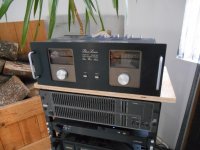
Hi Folks;
Just thought I would update you on the PL700 II. Amazingly the amp is performing beautifully after the following changes; (that were suggested to me, I just didn't follow them exactly, apparently)
-Chassis floating, no mains ground connection.
-amp connected to signal source by Unbalanced Coax.
I just had concern about connecting the amp with 62 VAC on the chassis, to the fancy miniDSP source. But it works!---and is dead quiet.
Attachments
I must confess that there was about 3 mV RMS of hum/noise on an 8 ohm speaker. This was reduced to 1 mV by the addition of a steel clam-shell shield installed above and below the control board. I discovered that lifting the board away from the AC hot wire, reduced the hum. I am convinced that the interference is capacitively coupled rather than inductively, as the phenomenon was present even when power was fed from the other side. Never the less, the shield was fabricated in steel.
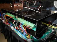
I am starting a rebuild of a second PL700 II and will verify the necessity of the shield.
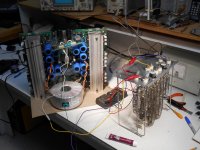
On to a side issue; it has pointed out that my dummy load (pictured below, ex electric furnace ) may have some inductive properties. The elements were reconfigured to be 8 ohms.
This may be basic electronics, but could I test this by connecting it in series with an 8 or 10 ohm carbon resistor, then measure the voltage at the centre point with my scope? If the voltage does not shift with frequency, would this confirm the suitability of the dummy load?
As soon as my wife is not looking, I will escape to my workshop and try this!
Attachments
- Home
- Amplifiers
- Solid State
- Power transformer leakage in Phase Linear 700