in thinking about your last post it corresponds to what i remember, amp needs to be grounded to be quiet/non humming and to be certain of conditions you where in fact driving it with a signal source that is grounded?
Last edited:
Hi Turk;
I have been studying my bible (Douglas Self, Power amplifier design) Looking like 42 uA through 1 Meg is OK. He DOES indicate that amp chassis should be grounded though.
Still puzzling: My old PL700 and PL700B are quiet with the chassis floating...
I have been studying my bible (Douglas Self, Power amplifier design) Looking like 42 uA through 1 Meg is OK. He DOES indicate that amp chassis should be grounded though.
Still puzzling: My old PL700 and PL700B are quiet with the chassis floating...
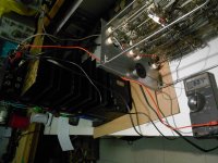
All seems fine again! Pictured is an IEC socket installed to replace the old permanently attached line cord. I was planning to leave the ground pin open but a 14 GA wire to the secondary centre tap bus seems to have solved the hum problem completely.
Tomorrow, hope to put this amp to the full power clip test to see what a 'WOPL' can do!
Happy New Year!
Tomorrow, hope to put this amp to the full power clip test to see what a 'WOPL' can do!
Happy New Year!
Attachments

I fully rebuilt a PL700b for a friend several years ago. I built the amp in one of the new 700 chassis that White Oak offered but I chose to revise the stock pcb's. The new White Oak chassis used a 3 pin IEC socket but I tied the AC mains ground to chassis ground. Then I tied the xfrmr secondary center tap (star ground) to the same chassis ground point with a 7 - 10ohm NTC inrush protector for isolation between the two grounds. That amp was completely silent.
The amp is dead quiet. No hum unless it is buried in the background hash viewed on the scope at max sensitivity.
Put the amp on the 8 Ohm dummy load; 60.7 VAC at 1 kHz, (460 Watts) Left of Right, just before clipping. Both channels still measure 0 mV DC offset.
..............Wow.........Can't wait to put this amp in my rack. Cleaned the meters, face-plate still needs work but I had to get a sneak-peek. The handle were from Home Depot, $3 ea.
Attachments

I think my celebrations were a little premature... There is a low level hum when the volume pots are opened. Dead quiet when pots are closed. Obviously the 'leaky' power transformer has got something to do with it but the amp. I am still hoping that this is a solvable problem.
even with no input connected, there seems to be more hum with the volume pot at 50%.
Fluke measures 1 mV at 50%....0 at min and max, nothing connected to input
Fluke measures 1 mV at 50%....0 at min and max, nothing connected to input
if i didn't know better (and i usually don't) i would think you may have cracked pots, the phenolic backplane is cracked as well as the carbon track but at a position that the wiper still see's ground when rotated fully counter clockwise.
the 1Mv measurement where is that being taken?
the 1Mv measurement where is that being taken?
Hi Peter,
If you check in some service manuals, they measure leakage by reading the voltage across a 1 K resistor connected between the transformer core and ground. Your transformer sounds like it is perfectly fine. Your hum could be the way it was originally wired, so don't ignore the input side of things. The core should be grounded to the chassis. Make sure it is.
The hum is greatest part way up because that is about where the impedance is the highest. So that isn't a clue - it is expected.
I did some work in the studio over the years with Dave Dickson. Aside from Dave, I mostly knew the studio manager but knew enough of Gil to say hi now and again. The amp you bought from the studio was likely from gear Gil bought from a different studio. They were using Crown DC300 amps mostly for their own installations.
Dave dropped from sight a number of years ago. Have you heard anything about him? He is someone who is always welcome in my lab.
-Chris
Hi Turk;
This is not the first time I have been accused of being a 'crackpot'. I was just puzzled that the noise was less with the pots wide open. The 1 mVAC was measured across an 8 ohm speaker connected to the amp output.
Hi Chris; My 60 VAC 'leakage' is not on the core. It is from the primary winding neutral side to the secondary centre tap. I will measure this voltage with a 1 k shunt. I measured 60 or 62 with Fluke only, 42 VAC through 1 meg, I believe it dropped to millivolts with 10K
A minor issue -- was reading Rod Elliott's commentary on ground loops Earthing (Grounding) Your Hi-Fi - Tricks and Techniques
-- is the transformer itself in electrical contact with the chassis?
I used a ground loop breaker in an F4, Pass used a Thermonetics inrush limiter.
-- is the transformer itself in electrical contact with the chassis?
I used a ground loop breaker in an F4, Pass used a Thermonetics inrush limiter.
A dim bulb tester will allow you to power up a piece of gear under test at minimal power... but it is NOT a line isolation device. For that you need what is called a Variac... a variable transformer that isolates the device from ground.
THIS line isolating variac tranformer is what you need to do the job properly. (Click on the word "this")
Are you sure that variable transformer also isolates? The description makes that claim, although the title does not.
Everything I know and have read about variable transformers is they are most definitely NOT isolation transformers.
I know that MY variac is just a variable auto transformer, not isolating. But the power transformer in the Phase Linear SHOULD be isolating. With the primary connected to the line, I'm getting 60 VAC on the secondary centre tap.
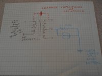
I am going to perform the following test, asap, on the transformer of my second amplifier, which is exhibiting the leakage.
If the leakage is due to inter-winding capacitance, I should measure leakage even with only one leg of the primary connected (?)
I am going to perform the following test, asap, on the transformer of my second amplifier, which is exhibiting the leakage.
If the leakage is due to inter-winding capacitance, I should measure leakage even with only one leg of the primary connected (?)
Attachments
Hi Peter,
I have never measured a transformer like that. I do tend to think that your leakage is real, and also within safety limits.
Sometimes your circuit common has to be isolated from the earth ground with a 10R to 100R resistor. The earth is still bonded to the chassis, so nothing that could possibly risk a shock or run afoul of the electrical code. All you are doing is lessening any current to ground while maintaining the potential. The core of the transformer needs to be well grounded to the chassis or it may radiate hum. I have greatly reduced the hum on several audio devices by cleaning up that transformer core connection to the chassis. If you have it shock mounted you will need a heavy wire (to carry any fault current possible in case the primary insulation breaks down).
Good luck on this Peter, Chris
Hope to do some testing on the transformer of the second amplifier today. Megger testing would certainly yield some worthwhile info but both transformers are presenting issues under normal line voltage conditions.
Can these transformers be re-wound? I have called a couple of shops in Barrie Ontario, no luck. This may not be an economically logical way to go, but has anyone heard of it even being possible?
I have heard that these amplifiers were originally designed to meet a cost parameter of one dollar per watt plus $99. Is it possible that transformer insulation might have been part of the cost restrictions?
The leakage in the transformers seems completely normal. The only way to get less with a transformer that large is to use a split-bobbin unit. Which would have terrible voltage regulation, and convert your amp from 350 watts per channel to around 200. Most amps this size just cover it up by using a grounded power cord, which would make your ground loop problems even worse. Try the trick of isolating the audio ground from earth with the 100 ohm resistor and hopefully it helps. In smaller installations with only a handful of pieces of equipment in the rack it often is.
When I used them in PA work I ended up replacing the op amp in the front end with a 353, on a little daughter board. Used the second op amp to add balanced inputs. Replaced the RCA jacks with 1/4” TRS. Problem solved permanently. The other alternative was to use very expensive full audio band input coupling transformers which I didn’t have the budget for in those days.
When I used them in PA work I ended up replacing the op amp in the front end with a 353, on a little daughter board. Used the second op amp to add balanced inputs. Replaced the RCA jacks with 1/4” TRS. Problem solved permanently. The other alternative was to use very expensive full audio band input coupling transformers which I didn’t have the budget for in those days.
Hi Peter,
Alternator and motor rewinding shops used to rewind transformers. Transformer manufacturers would look at the original one and wind you a new, better transformer. Hammond Manufacturing would do an excellent job for example. However, it wouldn't be cheap ad would only make sense if you had a few to do. A bunch for other PL700 owners would make sense. Just consider though, at the end of the day your power transformers are okay. Hammond transformers would be better, but there is a cost associated with setting up for the run, and taking the original apart. They might be able to wind one from the specifications, such as the AC voltage at idle and expected current draw. They would make a larger one that ran cooler and had better voltage regulation. They could also add an electrostatic shield (this is good). To start that conversation off, give them the no load voltages, size of core and the power output of the amplifier, plus the weight if you could get it. That will give them some rough idea of material costs. Give them one to make certain the new one would fit. You will get it back.
-Chris
Hi wg_ski;
Maybe this is good news. I have measured the 'leakage' on my second PL700 II and found a little less (53 VAC, dropping to 39 VAC with 1 meg shunt) The amp in question has 62 VAC, (42VAC with 1 meg shunt) The amp with higher leakage has some corrosion evident.
I have just measured a third amp (PL700B) currently in my system, powering midrange.
This amp measures 43 VAC, 29 VAC with 1 meg shunt. This is measured from the speaker neg terminals (which is transformer secondary centre-tap to wall outlet neutral) This amp has absolutely no hum issue. It is rack-mounted but isolated from rack by sleeves and shims. It has a White Oak control board.
I don't like the transformer coupling solution, kind of a contradiction to the PL direct-coupled philosophy in my uneducated opinion.
Hi Chris;
I was surprised that my older PL seems to function perfectly with the above mentioned leakage. The PL with the worst leakage seems to have some noise issues even with the inputs disconnected and a 10 K ohm resistor across the input terminals on the White Oak control board. I am going to investigate transplanting the transformer from the 'lower leakage' PL700 II.
- Home
- Amplifiers
- Solid State
- Power transformer leakage in Phase Linear 700