Good thinking. While the clips are removed a hole an be drilled and M3 thread can be applied. Works better in the long term.
Having the hole already applied makes it way easier than applying the hole afterwards.
Having the hole already applied makes it way easier than applying the hole afterwards.
Last edited:
I’ve put a note about replacement P/N for the main heatsink at the first post. 👍
Drilling and tapping the heatsink provides very tight thermal connection, but clip is adequate as well (performing well for years in my amplifiers).
Jean-paul’s solution: https://www.diyaudio.com/community/...ilter-and-super-regulator.420933/post-7888880
Drilling and tapping the heatsink provides very tight thermal connection, but clip is adequate as well (performing well for years in my amplifiers).
Jean-paul’s solution: https://www.diyaudio.com/community/...ilter-and-super-regulator.420933/post-7888880
Maybe it is a good idea to check the amplifier with that requirements. More than 250W dissipation to produce a few Watts in 2 loudspeakers seems non optimal. 250W also will require large heatsinks and fans (the nasty neighbour in audio). The circle one should not enter 🙂
Still hoping for a native R60 (targeting 60V primarily), even though this circuit has performed well at 58V.
The board is a little tight for heat sink fittings in that configuration.
The board is a little tight for heat sink fittings in that configuration.
Top output voltage is about 60 – 62V. It’s not related to any component approaching safe voltage limit but simply reaching designed adjustment threshold, before D1 starts to conduct current. Using R8 = 4K7 and R9 = 3K6 (part available), top voltage will be increased to 64 – 65 V.Still hoping for a native R60 (targeting 60V primarily), even though this circuit has performed well at 58V.
Yeah, TL431 is interfering with Q8 heatsink. Solder TL431 in low position and rotate Q8 heatsink that its wings go around potentiometer.The board is a little tight for heat sink fittings in that configuration.
Next time, I'll use SMD version of TL431. 🙂
Next time, I'll use SMD version of TL431.
That would be nice, but I could also use both sides of the board and distribute the parts.
I should have thought better when I built the first one, although if mounting the part that dissipates the most on a beefy sink, it kinda eliminates one side of the board as real estate.
That being said, I didn’t measure that clip-on heat sink getting very hot at all.
So maybe I am just a worry wart.
Hmmm....so the thought of a further refined 'Rxx' psu has crossed your mind, Tombo??Next time, I'll use SMD version of TL431. 🙂
Maybe a bipolar psu circuit on a single board 🤩.
Hah, yes. I still haven’t decided what to build next from amplifiers and that would determine next supply required properties. My current power amplifier is so good (subjective opinion, of course, valid for me only) that I have a hard time to decide on new direction. Kind of ultimate class D is also a serious contender. Next supply will be, for sure, dual rail (positive and negative) on one board.
Anyway, I’m for the next several months occupied with a different kind of DIY. I’m setting up a new hobby workshop in the basement and plan to do a total reconstruction of my mans cave to a dedicated listening room with acoustic treatment. Lot of work for two hands.
Anyway, I’m for the next several months occupied with a different kind of DIY. I’m setting up a new hobby workshop in the basement and plan to do a total reconstruction of my mans cave to a dedicated listening room with acoustic treatment. Lot of work for two hands.

Sounds like a great plan Tombo!
Basements can be made into fantastic spaces to spend lots of time in, lots of work indeed.
I have a nice spot in the basement for my DIYA tinkering, but decided to up and take over the dining room so my family still remembers my name 🤣.
Basements can be made into fantastic spaces to spend lots of time in, lots of work indeed.
I have a nice spot in the basement for my DIYA tinkering, but decided to up and take over the dining room so my family still remembers my name 🤣.
If it goes that way, it will be Purifi module + my custom input buffer design and linear regulated supplies as one compact board. There is no way I can design a better class D than Bruno Putzeys.
All 4 modules completed now and appear to be working. Hooking up the positive side to ground made me a bit nervous but it made a negative rail no problem. I did run into one gremlin, the one module appeared to be oscillating with voltage going from 4.5v up to 24v and then back down. Tested everything and finally figured out I installed the opa828 backwards, oops. Fixed and it works great now. I found these modules easier to build than the r21's.
Attachments
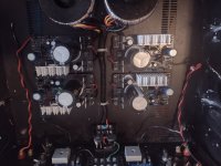
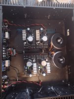
Well done and love the silver heatsinks as a nice contrast to the black pcb.
I had one of my R21 regulators oscillate as well. I checked everything of course, transistor checks, orientations, etc…and it was just a slightly cold joint (I suspect) on the series mosfet. Added a slight touch with my soldering iron and everything was back to normal.
Best,
Anand.
I had one of my R21 regulators oscillate as well. I checked everything of course, transistor checks, orientations, etc…and it was just a slightly cold joint (I suspect) on the series mosfet. Added a slight touch with my soldering iron and everything was back to normal.
Best,
Anand.
Thanks, the silver heatsinks where on sale for around 5.75 cdn on Newark so thats why I got them.
It previously housed F6 modules but I am hoping to somehow complete a set of USSA-3.2's. Waiting for profusion laterals and the knowledge to finish off the boards 🙂
Dropping +/- 82V to +/- 15V max. 1.5A and also +/- 50V max. 0.5A is designing exclusively in errors. There will be extremely much useless heat generated by the PSU only for no good reason at all. With the described maximum of 1.5A this would be a whopping 200W just for the +/- 15V. Even with a preamp drawing only 250 mA there will already be lost 33W to heat! With just 100 mA still 13W and with 50 mA 6.7W. All this without the +/-50V PSU that also will like to contribute to generating heat also for no valid reason. It seems the "potential issue" is a stove generating so much heat that will definitely will need to be given to the environment with forced air so with our best friends: fans.
A separate toroid for the +/- 15V would already be way better. Losses to heat could then be under 1W at 50 mA load current.
This PSU is the absurd opposite of one of the main design parameters of R25.
A separate toroid for the +/- 15V would already be way better. Losses to heat could then be under 1W at 50 mA load current.
This PSU is the absurd opposite of one of the main design parameters of R25.
Last edited:
You and I have discussed this in a different forum and I thought you said the transformer you were planning to use had a 17V tap. That would be a much better choice to derive the 15V rails from!
For reference, you can estimate the power lost to heat using this formula:
Pheat = (Vin - Vout)*I
With the 17V RMS transformer, you’d dissipate 13.5W at 1.5A. I doubt the preamp really draws that much (I estimated maybe a 100-200mA at the most based on the schematic you showed me), so you’d be just fine. But dropping from 82V? No way, Jose!
I would personally like it to be in the single digits or even the low single digits. 100W per rail is simply not workable. You’ll need a heat sink the size of a wood burning stove (OK, maybe not, but you need a big heat sink). And for nothing.
- Home
- Amplifiers
- Power Supplies
- Power Supply with Active Rectifier, RF Filter and Super-Regulator