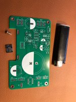
R25 board El Cheapo version. Indeed a large board but not too large 🙂 Normal copper, tin/lead finish. More than enough for the average sub 50W stereo class D amplifier. Since building costs are much higher than the cost of the device it will be feeding I decided to save a little and skip the (IMHO) silly and expensive clip on heatsink and will mount the MOSFET against the cast aluminium casing. With M3. Old fashioned sturdy, reliable and cheaper.
If someone in F, B, D or NL wants a PCB please send a PM.
Disclaimer: don’t lick or eat this PCB as it is not ROHS.
If someone in F, B, D or NL wants a PCB please send a PM.
Disclaimer: don’t lick or eat this PCB as it is not ROHS.
Attachments
Last edited:

That way is also recommended if anyone needs to take advantage of very high current capability.I decided to save a little and skip the (IMHO) silly and expensive clip on heatsink and will mount the MOSFET against the cast aluminium casing. With M3. Old fashioned sturdy, reliable and cheaper.
This time I haven’t included a build guide, but R21 build guide has such MOSFET mounting option pictured.
Yeah heat must not build up inside a casing. Better conduct it outside the casing and use that (already available so no added cost) large surface to benefit. Too many plusses really.
I was fearing the SMD parts but for some reason (are the pads elongated?) they seem easy to deal with on Tombo's board.
Yes, all SMD pads have prescribed dimensions for soldering by hand. SMD parts can still be soldered with hot air gun, except RF filter that must be soldered by hand.
Tombo,
Just read AGAIN the R21 build guide and noticed the recommendation for the heat sink for Q9 - with 38 volts entering the regulator and expectations of 3 to 3.5 amps being sent to the THF51 should I consider using something other than the suggested OHMITE part? I am terrible at understanding dissipation.
Your help would be appreciated.
Thanks,
That Ohmite probably won’t cut the cake with 3.5A continuously at 2V set dropout voltage. Rough guesstimation says approx. just about plus or minus more or less around 7W dissipation.
Last edited:
I think you are good with Ohmite heatsinks. Jean-paul is right that they are fancy but not everyone will have option to use case as a heatsink.
Power dissipation over regulator part is direct product of load current and voltage drop. It is likely that you will be able to use less than 1.5 V voltage drop. At 3.5 A load, dissipation will be 1.5 x 3.5 = 5.25 W. Heatsink is specified to have 3.3°C/W, but > 6°C/W is what I measure as worst case. So, you can expect that heatsink temp. will rise for about 35°C above ambient. Even inside hot amplifier case, that is not a problem. Design is such that heatsink temperatures up to 85-90°C are not a problem, but it is better if temperatures can be lower, say up to 65°C.
AFAIK, you have open ‘case’ for amplifier, so even less dilemma.
Yes, it is WIDE open! Thanks to you both but especially to Tombo - I think I get dissipation now.
I remember you saying that the output device did not mind the heat.
I had read that those clips as on the OHMITE heat sink were superior to nuts and bolts but I have taken note of your advice on bending the spring for more pressure.
Take care,
I remember you saying that the output device did not mind the heat.
I had read that those clips as on the OHMITE heat sink were superior to nuts and bolts but I have taken note of your advice on bending the spring for more pressure.
Take care,
P = U x I. Stuff in Volts, Ampères and Watts. So if you have 38V in and 36V out then it is 2V x the current. 38V in and 36.5V out is 1.5 x the current. Imagine having 1V at 100,000A or 100,000V at 1A. Power is the same (but you'll need fat conductors for the 1V situation). Less warm is better for all involved inhabitants in a casing. Only stuff warmer than 50 degrees I like is when it is on my plate. Whatever the possible/allowable maximum limits of parts, they don't live longer with higher temperature. In my field maximum allowable internal temperature for a longer time in devices is 70 degrees but I can assure those devices live shortest. They don't win first prizes in Miss Reliability contests.
Of course clamping by just 1 spring is nice and easy and all but it is just made for faster mounting and it is technically inferior to nut and bolt. Springs usually loose their power when they get hot or because of heat cycling. Quite many things previously discarded as technically inferior have won the race as they cost less time in production/repair.
Of course clamping by just 1 spring is nice and easy and all but it is just made for faster mounting and it is technically inferior to nut and bolt. Springs usually loose their power when they get hot or because of heat cycling. Quite many things previously discarded as technically inferior have won the race as they cost less time in production/repair.
Last edited:
Your advice is good - I know the clamp is an easy way to hold down the body of the device against the sink. I prefer using a piece of brass channel across the body and using two screws to make a very secure fixture. The screw in the top alone has always seemed compromised.
What would be neat is a piece of metal that would allow the use of just the screw yet be held firmly against the body of the part, too. Does someone make such a thing?
I have never used the clips before. Does seem like things would have to get really hot for the springs to be affected. I run my amplifiers for two to three hours in the evening so they are not exposed to long term heating.
In high power electronics sometimes the single screw method is not enough (vibrations, fault reduction, guaranteed heat transfer etc.) and then small steel U bars with 2 nuts/bolts left and right of the semiconductor are used over the casing tightened on exactly the right torque. Otherwise the semi casing will crack 🙂 I have leftovers but never use them in my audio stuff as I make pretty cool stuff. Pun intended. Very high power semiconductors often have a large surface metal mounting plate integrated with several mounting holes for even pressure and fault tolerance. It is mostly galvanized steel for tightening and aluminium for heatsinking. Of course with an army of screamers (high RPM ear piercing fans).
Brass is not rigid enough for clamping/pressure.
Brass is not rigid enough for clamping/pressure.
Last edited:
Brass channel for a TO220 in a power supply, which is where I use them? Come on, plenty rigid for that! I cannot get it to bend. It would break the body of the devices before it would bend! How much pressure do you put on your devices?
As written, power electronics with approved/certified/tested industrial parts tightened with the right torque. Not hobby stuff.
Just looked and also 1 screw number 7 shaped clamps are used spreading pressure over the entire TO220/TO247 tab + body.
Just looked and also 1 screw number 7 shaped clamps are used spreading pressure over the entire TO220/TO247 tab + body.
Last edited:
Something like those Aavid MAX08NG (or 07NG) transistor clips are very useful too - I had to get one of those tension adjustable screwdrivers for the bar mounting bracket for those little super jfets in the F3 amp - it did work (eventually!)
Thanks Rick, replied to your PM, thanks
Thanks Rick, replied to your PM, thanks
I came to realization I should use the same heatsink as the THF51 - it is an old Dynaco Stereo 400 heatsink and there is a good spot for the reg with the added advantage of placing the regulator really close to the THF51 but not so close to be heated by the thing. There is a fan blowing through the fins.
If there is enough place for supply on the amplifier’s heatsink, that is the best location. Using that big heatsink for supply’s MOSFET, provides adequate cooling in any conditions.
Not that it makes any difference but the specified capacitor for C6 does not have a 5mm pitch - it is 3.5mm. Just found out when I tried to insert it. Not that the leads cannot be bent and made to fit. Have done it plenty of times.
Before I solder them in - is this the capacitor you intended for us to use? Not trying to play "gotcha" - just want to be sure.
Thanks, Tombo
Before I solder them in - is this the capacitor you intended for us to use? Not trying to play "gotcha" - just want to be sure.
Thanks, Tombo
Wrong part number slipped in the BOM. 😠
Both shared Mouser cart and Excel BOM are updated.
Wrong C6 with 3.5 mm pitch can be used with just a little leads bending, left several mm above board.
From the technical standpoint, it is the right one – hybrid polymer with required properties.
Both shared Mouser cart and Excel BOM are updated.
Wrong C6 with 3.5 mm pitch can be used with just a little leads bending, left several mm above board.
From the technical standpoint, it is the right one – hybrid polymer with required properties.
- Home
- Amplifiers
- Power Supplies
- Power Supply with Active Rectifier, RF Filter and Super-Regulator