Terry, my experience with transformers is just sufficient to get me by with simulations, and the last time I looked at the matter to any degree was a couple of years ago. However, I had a quick rummage around my downloads of the time, and also just had a quick look around now via Google; and it appears that a standard power supply toroid of that rating has magnetising current in the ball park of the figure that you query.this transformer might turn out to be a TERRIBLE choice for modelling power supply interactions")
So, for better or worse, those are the order of transformer characteristics that the modelling needs to use, it appears ...
Frank
A typical answer for whom dont know an answer.Terry, thank you very much for your time and explanation, I would not say I am now qualified in the matter, but I have a far better grasp of where you coming from with your thinking of the power supply modeling.

Not to take anything away from Terry's excellent and comprehensive explanations ... for the tiny number of those not familiar with this material, there's also Inrush Current ...
Frank
Frank
Liching1952,
lets stop fooling with everyone, I don't think you are stupid, but I also do not think you totally understand what we are trying to argue here.
The question is to try to establish a simple set of rules that will mostly satisfy the power supply requirement of a typical DIY power amplifier, given rudimentary power requirements.
We are not trying to establish who is the smartest kid on the block but trying to learn from each other, especially from those in the knowing.
So far some members were really forthcoming by putting a lot of effort into the matter and I thank you all without singling out anyone. It has made this thread genuinely worth following and I again thank you all for your contributions.
What are your comments volks?
While you're chilling, the harmonics produced you do not want to hear or have them cause the amp go boom. Hence the NFB loopfrequency transient response must be capable of erasing those harmonics and otherwise intrusive transients to be suppressed down to below the noise level. You need a regulatory frequency at least 10 times the desired signal-to-be-reproduced-by-negative-feedback bandwidth to reproduce accurately. To do that, the logical system that is the closed negative feedback loop is going to need current when it wants to. Preferrably 'now' and not in a few units of time.
Andrew,
if we ignore core saturation, it pops straight out of the solution to V = L*dI/dt if we take the initial conditions into account. this is pretty easy to test in spice (where its kinda hard to model actual cores, which is amusing).
the thing is, unless you study network analysis (in say an EE degree) you will hardly ever come across initial conditions. they complicate everything, so are almost always ignored. and in EE its mostly covered in network analysis, so all the other fun courses casually ignore it too. hell, I ignored it right up until it bit me in the ****. now I specifically check for initial conditions I have to care about before starting an analysis.
hand-wavey explanation:
(I'm using electrical angles cos its less confusing).
in an inductor the current and voltage are 90 degrees out of phase. with zero-crossing turn-on (assuming no stored flux in the core), V(0) = Vpk*sin(0) = 0 and I(0) = 0. whereas in steady state at the zero crossings V(n*pi) = Vpeak*sin(n*pi) = 0 but I(n*pi) = Ipeak*cos(n*pi) = +/-Ipeak
so turning an inductor on at zero voltage effectively applies a transient step to the inductor current of Ipeak, which will decay with an L/R time constant. so the peak inrush current can be twice the magnetising current.
Any residual magnetism in the core will either add to this, making it worse, or subtract from it, making it better.
when you include xfmr saturation this gets a whole lot worse, as L drops a lot and I skyrockets - my 400VA variac has an isolating transformer, and the bloody thing occasionally pops a 10A breaker (yeah, I know, but its easier to flick the breaker than pull the variac out and put in a soft-start. one day.....)
if the xfmr fully saturates then Lmag = Lp_leakage = bloody small, and that along with Rp are all that limit the primary current.5% - 10% is typical for a mains transformer, so 10x - 20x inrush currents result.
its for this reason that many xfmrs have a small gap. this reduces Lmag, increasing Imag, but ensuring the transformer doesnt saturate reduces the inrush current from 10..20xImag down to 2xImag.
google high voltage inrush limiting resistors. these are AWESOME and are in series with humongous power transformers in substations etc.
here's a better analysis: http://xa.yimg.com/kq/groups/233494...rush+current+in+a+single-phasetransformer.pdf
Last edited:
"resting"
What a shame, for the occasional sTroll-in, he/she was refreshingly amusing.
Frank,
yeah, Rods site is great, and he's pretty good with the technical details, although he tends not to be all mathematical. thats the cool thing about electronics - the practical is at least as important as the theoretical, if not more so.
re. initial conditions - I got really good at laplace transforms years ago. if we ignore initial conditions its actually just algebra, right up until we have to do inverse transforms. which we hardly ever do - the frequency response is usually the desired goal. Other than in maths classes at Uni, I dont think I have ever done an inverse laplace transform analytically - I use an optical-neural pattern-matching heuristic for inverse transforms (I look through a big book of laplace transforms until I see an s-domain function that matches what I have, then write down the time-domain column).
that served me well for 15 years as a power electronics engineer. until one day initial conditions became really important, and I suddenly realised I had to go back and learn how to do them.
And herein may lie the great answer as to why negative feedback in many implementations seems to fail to live up to expectations, why it has such a bad rap ...Hence the NFB loopfrequency transient response must be capable of erasing those harmonics and otherwise intrusive transients to be suppressed down to below the noise level. You need a regulatory frequency at least 10 times the desired signal-to-be-reproduced-by-negative-feedback bandwidth to reproduce accurately. To do that, the logical system that is the closed negative feedback loop is going to need current when it wants to. Preferrably 'now' and not in a few units of time.
Frank
Frank/MagicBox,
This is in fact an excellent argument that can be added to an already complex problem, in that the negative feed back now introduces power supply related crap into the signal, especially so if the front end is better regulated than the back end. So where do we draw the line and what are we actually listening to.
For all we know amplifiers all sound exactly the same and we are just barking up the wrong tree, it is power supplies that sound different.
Heck, I cannot actually believe that one can hear such miniscule amounts of distortion of whatever order - just look at most sims because they assume a perfect power source therefor the amp design is probably near perfect, but I bet we are hearing power supply modulation.
If one looks at the simple model of an opamp driving a complementary pair of output devices, then we can see the nfb problem. When the v+ & v- voltages are not applied to the bases of the output devices we can see the voltage "jumps" that the opamp has to attempt to try to get a smoothly flowing sinewave at the output.
LTspice could sim the currents required to achieve those instantaneous "jumps". They will be colossal in terms of opamp capability.
Could one of our LT experts do that sim for us to "see" how big the problem is? i.e. what the feedback forces the opamp to achieve and where the current comes from, in trying to get those "jumps" to be near vertical.
I would expect the "speed" of these jumps to require response in current terms approaching and probably exceeding the few MHz range.
Last edited:
On the very first page of the thread and what actually prompted me to start the thread
Could it be that I actually listened to the amplifier instead of the power supply.
.........
On the week-end I replaced the SMPS with 2 x12V 22.5Ah gel batteries and the"improvement" again, chalk and cheese.
Could it be that I actually listened to the amplifier instead of the power supply.
Last edited:
Frank,
Thinking about it, and re-reading McLyman (the first 50 pages have some great pics and a discussion of this. If you want a decent analysis and a bunch of easy to apply cookbook formulae, W. McLyman Transformer and Inductor Design Handbook is quite good. especially for LF. I wouldnt buy a new copy though, its not that good - but 2nd hand its cheap, I have 2nd ed.)
EE or EI lamination xfmrs all have small air gaps at the E-E (or E-I) junction. Toroidal (wound) cores do not have any air gap. even 25um has a sizeable effect on saturation, so toroidal (wound) cores saturate a lot faster then EE/EI cores.
one solution is to cut the wound core, lap & etch the ends to remove smeared-over metal and then glue them back together - so-called Cut Cores. as can be seen from the image, this has a major effect on inrush current. (we once had some Honeywell metglass cores in a 300kW inverter that were insanely lossy - we eventually found Honeywell had forgotten to do this, and the cuts (two per core for 4 gaps) had shorted the iron, so the core loss was astronomical).
another solution is to run the core at a low flux density, which requires more turns and/or core area, has low magnetising current but high leakage inductance and resistance. As such I am inclined to think that the core runs at very low peak flux.
Attachments
Last edited:
Nico @ #551
that sounds reasonable. I, too, think MagicBox & Frank have, shall we say, opened the box and exposed the magic. fits in well with the discussion to date on psu HF transient response.
Edit: and the corollary is that poor HF layout on the PSU-to-amplifier power train* really gives the "opamp" a hard time as it maximises the bandwidth required to compensate for the poor HF response of the PSU.
*(and in the amplifier itself, although the PSU-to-amplifier power train probably dominates as it it so often done appallingly badly)
Nico @ #554 that made me laugh!
lousy layout maximising required BW = lose-lose scenario - bad layout is unlikely to be confined to the PSU alone. unless one got a well-laid out PCB then added a crappy PSU to it - in which case a few gel cells would indeed make a sizeable improvement.
here's a stupid idea: fix droop with a couple of gel cells in parallel with the dc bus caps. yay, a way to make amps heavier.....
that sounds reasonable. I, too, think MagicBox & Frank have, shall we say, opened the box and exposed the magic. fits in well with the discussion to date on psu HF transient response.
Edit: and the corollary is that poor HF layout on the PSU-to-amplifier power train* really gives the "opamp" a hard time as it maximises the bandwidth required to compensate for the poor HF response of the PSU.
*(and in the amplifier itself, although the PSU-to-amplifier power train probably dominates as it it so often done appallingly badly)
Nico @ #554
that made me laugh!lousy layout maximising required BW = lose-lose scenario - bad layout is unlikely to be confined to the PSU alone. unless one got a well-laid out PCB then added a crappy PSU to it - in which case a few gel cells would indeed make a sizeable improvement.
here's a stupid idea: fix droop with a couple of gel cells in parallel with the dc bus caps. yay, a way to make amps heavier.....
Last edited:
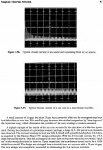
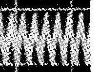
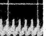
Inrush Plots @ #555:
you can actually (OK, barely) see a couple of interesting things in the 2 plots. close-ups attached.
Upper plot: inrush peak = 3divs, steady-state peak-to-peak = 1/2 div.
but notice the shape of the waveform - its very peaky, kinda looks like a small sinewave, with a nasty peak added to each half-cycle. which is exactly what it is - the nasty spiky peak is the core saturating, Lmag dropping and Imag rising - very fast.
really without the saturation spike Ipeak should be more like 1/3 div.
Lower Plot: inrush peak = 1divs, steady-state peak-to-peak = 1 div.
so the inrush has gone, but the peak mag current has doubled - Lmag went down.
and notice the shape now - its much more triangular and less spiky. this is because the core isnt moving into saturation.
Attachments
Yes!If one looks at the simple model of an opamp driving a complementary pair of output devices, then we can see the nfb problem. When the v+ & v- voltages are not applied to the bases of the output devices we can see the voltage "jumps" that the opamp has to attempt to try to get a smoothly flowing sinewave at the output.
And now you say this, I can add a next bit of issue with an inherently symmetrical design, which is that there are two cases of equibrilium; positive eq (your class B opamp keeping a zero output with a zero input leaning positive equi (the N transistor is just barely conducting enough to keep it zero, single quadrant operation)) and the corresponding negative equiThey are separated in class B while in class A operation they converge, that why you get the erratic jumping at the crossover, it's the constant toggling between the positive and negative equibrilium of the feedback loop. By destroying these 'deadzones' you can have the control signal reach an uniform equibrilium with which it reproduces the audio signal.
Could this be the reason that amplifiers with only "local feed-back" and no overall negative feed back said to sound better
Yes, when it comes to distortion products like generated harmonics. The local NFBs are much shorter (most of the time just 1 device) and hence can maintain a regulatory frequency higher than NFB applied globally.
Due to the lack of global feedback and the less than ideal linearity of a single device with local feedback, the signal integrity *is* affected although this is a more 'pleasing-to-the-ear' kind of deformation; it's nothing but an ever so slight amplitude modulation at signal frequencies. But it's an alteration nonetheless.
When both local and global feedback are used you can get the best results I think. Local feedback ensures local highfrequency stability at each stage, allowing one to push the global NFB further (lower Cdom), and thus increasing the overal response of the amp, gaining both active distortion suppression with accurate retention of the original signal.
This is the principle I applied in my MF80 design, with a symmetric BC550/560 C grade IRF510/9510 cascoded darlington VAS and local feedback. It's all stable and the sound... well. Paired with a proper speaker, it sounds great, but I'll save you the superlatives trying to describe it lol.
PS: The 'regulatory' frequency I've been talking about all the time is the stable-unity-gain bandwith frequency.
PPS: This is just my opinion
Last edited:
Terry, another Dutch guy has been putting a lot of practical research into this subject as well and did some very interesting measurements on inrush. It's a dutch language thread but maybe you can pull it through Google translate. Freddy shows.. The scope pics are very telling
Last edited:
- Status
- This old topic is closed. If you want to reopen this topic, contact a moderator using the "Report Post" button.
- Home
- Amplifiers
- Power Supplies
- Power Supply Resevoir Size