Hello dear fellows,
I am going to make a custom power supply for AA DDE v3.0 as I acquire the device without.
As far as I uderstand this device use both rails +/- 18v and +/- 8v and would like someone to reconfirm the pinout voltages and grounds as in the service manual the pinout is showed, but voltages are not mention, nor the perspective of view (my concern) - the diagram shows device inlet or pinout of the power cable? The pinout and measurements would be the same for all power supplies sharing 6 pin DIN plug so it should be PS2, PS3, PS4, which may help us to measure and confirm pinout positions of the cable.
Can someone help me please. Would be very gtateful and rely on your extensive expertise!
Thank you inadvance!
Kind Regards
Dimitar
Attachments
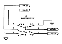
It is a drawing of the power entry input connector. If you want to be sure and prevent a fatal mistake (which simply is good thinking) you must open the device and see which pins go to which voltage regulator. It will be clear within minutes.
If unsure post a picture and it can be determined. The schematic is also quite clear. Edit*: the schematic is not so clear!
* It seems to have both 5V and +/- 12V regulators on the digital power supply lines so these can not be +/- 8V. The analog power supply line seems to also have 5V regulators. This may indicate some drawing irregularities. I would examine carefully what is connected to what.
Attachments
Last edited:

We just wire the power supply and connected, but it burns unfortunately... we found that there is somewhere link between digital ground and analog ground in the circuit. Is this normal? What should I do now? 😞ItIt is a drawing of the power entry input connector. If you want to be sure and prevent a fatal mistake (which simply is good thinking) you must open the device and see which pins go to which voltage regulator. It will be clear within minutes.
If unsure post a picture and it can be determined. The schematic is also quite clear. Edit*: the schematic is not so clear!
* It seems to have both 5V and +/- 12V regulators on the digital power supply lines so these can not be +/- 8V. The analog power supply line seems to also have 5V regulators. This may indicate some drawing irregularities. I would examine carefully what is connected to what.
It is a drawing of the power entry input connector. If you want to be sure and prevent a fatal mistake (which simply is good thinking) you must open the device and see which pins go to which voltage regulator. It will be clear within minutes.
If unsure post a picture and it can be determined. The schematic is also quite clear. Edit*: the schematic is not so clear!
* It seems to have both 5V and +/- 12V regulators on the digital power supply lines so these can not be +/- 8V. The analog power supply line seems to also have 5V regulators. This may indicate some drawing irregularities. I would examine carefully what is connected to what.
1. "The" PSU....A DIY PSU?
2. Did that PSU give 4 voltages simultaneously at power on?!
3. What were the voltages* you connected to +Va, -Va, +Vd and -Vd?!
4. Did the real situation look exactly like the schematic?
Yes of course there is a connection of kinds between both Agnd and Dgnd.
*It is a technical forum so please mention what voltages were connected to what pins. No a burning PSU is not normal. If you want to be told what to do you should not first power it on. First think, exclude failure possibilities, ask for verification (as more or less offered) and then power on. Or gamble.
Thank you for you dedication. I really appreciate it! The pins of the cable plug was wired with 2 bipolar voltages according to the picture. They were measured and crosschecked before connection was made. When plug it and power the supply ... all leds on the dac start to run from down to up (some check probably?) but then after second all lights dissappear and there were no voltages - my divider was burnt - I made from +32v => +/-18v and from another rail +16v => +/-8v
Attachments
Hi mate,
Let me explain the chain.
I used switching power supply of 20v and then step up for 38v rail and another with step down for 16v. After that I put two dividers like these
https://elimex.bg/product/48604-kit-k148h-preobrazuvatel-ot-ednopolyarno-v-dvupolyarno-naprezhenie
in order to receive from the first line +/-18v and from second line +/- 8v, then connect to the pinouts.
After the try the transistors of the dividers burnt, but I suspect that the elements are not so quality despite they get very hot for a 30 seconds work.
I think DDE v3.0 has no more than 300mah consumption of a rail, so I guess if I put more powerfull transistors the scheme will work.
After I restore one of the dividers I try only with the +/-18v (digital voltages) rail and power the unit and the lights goes on and I can switch the inputs and the phase button works as well, but when I put optical cables in, there is no "lock" light up ... obvious from the lack of the analog power supply I guess. The transistrors again got very hot but still works after 1 minute work, so I really guess the burnt when both rails are connected is because of the common shortage of the digital and analog ground?
What you think?
Kind Regards
Last edited:
I think it are too many words and few serious user errors.
5. You need true symmetric PSUs. Nothing switched, nothing with virtual middle point or dividers no just real symmetric PSUs. The simplest of all possibilities.
6. So a transformer with double secondary winding and 2 of them both with rectifier bridges filter caps and +/- voltages.
7. This circuit both for +/-18V and one for +/- 8V (which we already concluded that is an error, reread post #5).
8. This would be a 2 x 12...14V transformer likely a 10 VA type and a 2 x 7V 10VA type but the latter should be verified as there are 7812 regulators connected according the schematic. 7812 does not work with lower input voltage that its regulated voltage.
All in post #5 and numbered but unanswered. It is give and take here. Please write electrical units the technical and correct way. V, mA etc. mAh is wrong that is energy not power.
Attachments
Last edited:
Can you please point out some suitable and available examples to choose from?
Sorry for the too many words 🙁
Symmetric or asymmetric?
Sorry for the too many words 🙁
Symmetric or asymmetric?
An expert in too many words myself and that is not the point. The point is too many words spent on a non solution. It needs 2 symmetrical PSUs and either 1 transformer with 4 windings (rare) or 2 transformers with 2 x XV windings. Plus 2 diode bridges and 4 filter caps. The simplest of all possibilities.
The "first action, then present my self caused problem on the forum" approach can be modified with only slight modifications for better and cheaper performance to "first present on forum, ask if what I am going to do is OK and then action" model. The panels generally rate that model way higher.
The "first action, then present my self caused problem on the forum" approach can be modified with only slight modifications for better and cheaper performance to "first present on forum, ask if what I am going to do is OK and then action" model. The panels generally rate that model way higher.
Last edited:
Thanks,
How can be sure that the shorted VG and AG (somewhere) is the original state of this device?
Have you seen on the diagram such thing ... me not ... what is the purpose to differentiate them everywhere once I check the pinouts are shorted at the device power socket 🙁
How can be sure that the shorted VG and AG (somewhere) is the original state of this device?
Have you seen on the diagram such thing ... me not ... what is the purpose to differentiate them everywhere once I check the pinouts are shorted at the device power socket 🙁
You mean AG and DG (normally called Agnd and Dgnd). That is because they maybe are one and the same or maybe they are connected one way or another (very likely). In our field we measure this with a DMM in resistance mode and then say "Aha".we found that there is somewhere link between digital ground and analog ground in the circuit. Is this normal? What should I do now? 😞
If you caused a defect by connecting electronic dividers* and stuff and you now have shorts between either + and - or + or - to either GND then the device possibly is kaput.
I used switching power supply of 20V and then step up for 38V rail and another with step down for 16V. After that I put two dividers like these
https://elimex.bg/product/48604-kit-k148h-preobrazuvatel-ot-ednopolyarno-v-dvupolyarno-naprezhenie
*Your voltage dividers will divide and then the middle point is half the original voltage. This is by far not the same as GND/0V. The absurd way it has been executed maybe executed the device.
Last edited:
We recorder the short between the Agnd and Dgnd before we thest anything.
After the tests when the device is barely powered only with +/-18v is responsive in the scope of digital part.
I am afraid only for the "lock" light which doesn`t ligh up when inserting the optival cable in the device. Is it normal the device not to lock the signal without analog rail supply?
Thanks
I may be wrong, but what I see in the schematic is the need for two +-18 Volt supplies. This means rectified DC, not just an AC transformer.
So out side the DAC you need 2 transformers with 12V 0V 12V each.
Each transformer needs a bridge rectifier and 2 capacitors of 25 Volt /4700uf.
Now you have to connect six (6!) contacts: Digital +18 Volt, Ground -18 Volt and
Analog +18 Volt, Ground, -18 Volt
If you connected AC or the wrong polarity, concider the DAC to be burned toast.
Ps the primary AC of the transformers may be better 15 Volt instead of 12 Volt.
No one said just an AC transformer. Voltage dividers were used (see post #8) with assumption that the middle point is 0V and the PSUs suddenly became symmetrical ones. They are not. Now suppose 2 of such contraptions are connected with their middle points to a joined GND/0V point......... One of them being around 19V and the other 8V..... късо съединение
2 x 15V 10VA means around +/- 22..23V in reality with light loads. 2 x 12V secondaries with 11DQ10 or the like Schottky diodes and 2 x 4700 µF seems a better bet for 7812/7912 but since I have both I simply try out in such cases. Less heat but a good margin are both welcome.
2 x 15V 10VA means around +/- 22..23V in reality with light loads. 2 x 12V secondaries with 11DQ10 or the like Schottky diodes and 2 x 4700 µF seems a better bet for 7812/7912 but since I have both I simply try out in such cases. Less heat but a good margin are both welcome.
Last edited:
Are we sure that need 2 rails of +/-18 volts?
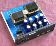
With lot of efforts I found an internal image of original AA power supply it looks like Power Station 2 (PS2) and it confirms 100% your guidlines and as far as I can see there is additional internal regulation there.
Noted the voltages recommendations! Don`t you think is good idea to get higher voltages and then regulate them?
Attachments
In post 2 you were pointed to check/verify and you still can do that to know stuff instead of assumptions. It really helps us when you want help and then reply to our questions as these are asked to solve your problem.
Preregulators were once normal but efficiency did not improve 🙂 It makes it way simpler though for you. You then need /- 18V generated with 2 x 18V transformers and this 2 times. For the digital supply voltages we still don't know for sure as you should verify if there are 7812/7912 connected to that supply lines. If so then you need a double +/- 18V PSU (with 2 transformers) so 2 x + 18V and 2 x -18V. Todays 7812/7912 would be OK with just 2V dropout so +/- 15V would then be more than enough.
Enough of my time, good luck with the repair.
Last edited:
Power consumption of the whole DAC should be quite low, so even a little higher voltage in the power supply will not be any problem.
Because of the old 7815/7915x regulators, 12 Volt AC may be a little on the low side ( 12V AC x 1.414).
So picking some 15-0-15 V AV transformer will be fine. The internal 15 and 5 Volt regulator will tollerate that. They are quite oversized for the little current draw of the components.
I build an external powersupply for a DITB / DAC-in-the-Box, because the factory ones all failed. I went with a 7818 +7918 as pre-regulator, followed by some additional filtering. OK, don't blame me for the wasted energy, was about 20 years ago...
I still like the DITB with this supply, which is larger than the DAC. The DITB was my first external DAC and at that time really improved some CD player I had. The sound of that simple thing leaves nothing to complain. Never heard it with the origional wall wart, but there were some not so nice comments about it. So my supply may have been a little improvement, who knows?
It does not have 7815/7915. The DAC has 7812/7912 internally that work just fine when fed ripple free and regulated +/- 15V. Since stuff got toasted anyway I would replace them for modern versions with 2V dropout voltage as they cost nothing.
Sorry, please go on.
Kovachev, post #5: 2. Did that PSU give 4 voltages simultaneously at power on?! -> it needs all 4 voltages for correct operation with true 0V middle points connected to their dedicated GND pin. It is so simple that it apparently becomes too hard to understand?!?
Sorry, please go on.
Kovachev, post #5: 2. Did that PSU give 4 voltages simultaneously at power on?! -> it needs all 4 voltages for correct operation with true 0V middle points connected to their dedicated GND pin. It is so simple that it apparently becomes too hard to understand?!?
Last edited:
- Home
- Amplifiers
- Power Supplies
- Power Supply for Audio Alchemy DDE v3.0 (pinout reading/measuring)