Hopefully you won't mind having a quick look at the grounding picture/modified circuit I will post a bit later to make sure I have understood all of your advice correctly.
Hello Andy
Im interested to see what your modified unregulated circuit looks like,
Any chance of posting this?
Cheers Dan
Not enough caps
In my opinion, you don't have large enough caps in the power supply - the old rule of the bigger the better. I built the Stochino fast amps (100W into 8R) and use 100,000uF per channel. I'm currently working on new anodized alumiunium cases for these amps and am going to upgrade to Mundorf caps, increasing to about 130,000uF per channel. Definitely increases dynamics and bass punch. Look at any high end amp and see what they use - usually big power supplies even for 100-200W amps.
In my opinion, you don't have large enough caps in the power supply - the old rule of the bigger the better. I built the Stochino fast amps (100W into 8R) and use 100,000uF per channel. I'm currently working on new anodized alumiunium cases for these amps and am going to upgrade to Mundorf caps, increasing to about 130,000uF per channel. Definitely increases dynamics and bass punch. Look at any high end amp and see what they use - usually big power supplies even for 100-200W amps.
Hi,
Shredly is of the opinion that regulated supplies can improve the performance of an amplifier by design rather than the brute force low technology route that many of us follow. He is possibly right, for some excellent regulated throughout amps have impecable performance with the advantages that you just listed, probably due to the very low PSU output impedance that is achieveable with a regulated supply.
However, the purpose of this thread is to find and cure a HUM problem. We cannot seem to agree what is causing the hum and until we have sufficient data to analyse, then it is going to be difficult to suggest workable solutions.
The simple fact is that some amps with 'mere' 10,000uF supplies don't hum, so there is no need IMO to go to such crazy levels of capacitance as 10x that, for this particular reason at least.
To clear things up for me, the hum problem that is being discussed is in the guitar amp whose schematic is posted in the other thread and not related to any of the amp regulators that are posted in this thread, correct?
If this is true, is there a diagram of how the grounds are actually implemented in the guitar amp? The schematic I'm examining doesn't say much as to how all of these circuit and input/output grounds are actually implemented.
It's tough to say lift the ground at the circuit imput and be doing anything other than guessing. The sequencing of the grounds and the loop layout can make all of the difference in the world.
mike.
Hi Mike,
you hit it on the head.
We have not seen the details yet.
All we have is a reverse engineered schematic that I have lost contact with.
But, our poster has got himself bogged down with regulated supplies.
you hit it on the head.
We have not seen the details yet.
All we have is a reverse engineered schematic that I have lost contact with.
But, our poster has got himself bogged down with regulated supplies.
AndrewT said:All we have is a reverse engineered schematic that I have lost contact with.
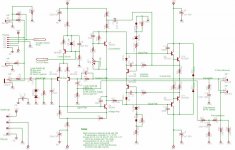
Here's the schematic.
Mike.
Attachments
OK, well, I did it, and it worked like I thought it would, except for a couple problems I'll get into shortly. The hum is definitely coming from the power supply, no question about it. The only hum I can hear now is coming from the reverb-- which is unshielded, another cost-cutting measure by the manufacturer, I think-- I replaced the cheapie cables to and from the reverb coil, and it helped, but there's still just enough to be irritating. Coil (aka "spring") reverbs, BTW, are infamous for picking up hum, both because they usually don't have a good faraday cage around the coils, and because you have to amplify the signal coming back from the coil a lot. I'll put a cage around it and that should take care of that. So you know, I put a florescent light about six inches above the top of the amp case, to see if the amp itself is well shielded, and properly grounded, and I could only just barely hear the difference with the light off or on, which is pretty darn good; with the original power supply in there, the hum it already made was quite a bit too loud to hear the difference, so that'll give you an idea how much hum it was.
However, it appears that I don't have enough capacitance on the input- it's browning out at the top end. IOW, if I keep the gain and output level on the preamps down, it sounds awesome- but if I crank it up, it drops out if I hammer a power chord, and comes back when the chord quiets down just a bit, about 300 or 400ms into the attack; interestingly, this seems more prevalent at the top end, whereas one would expect the bass to demand more real power, being lower frequency and therefore staying on one side of the pushmepullu longer. It also has startup trouble- it won't come up properly if the speakers are connected when I turn it on, but if I disconnect the speakers, power it up, and then connect them, it works just fine.
I think 5A isn't enough for this amp. I could gang two regulators to get 10A to fix the startup problem, you can either use a pair of resistors, or, if you're finicky, you can use an op amp to get them to track, and I could probably take care of the brownout problem by that and increasing the input capacitance, but if I'm gonna use two regulators I can get almost as much power (8 or 9A) in less space using a pair of 2N3055-based discrete regulators with foldback current limiting; I'll use the circuit I posted a couple pages back, more or less. Two TO-3 cans instead of four; the rest of the components except for the smoothing caps are all small, the largest other than the pass transistors will be the MJE3055s in TO-220 cases that I'll darlington with the 2N3055s to boost their beta high enough to give me the output I want. If it were just one problem or the other, I might try to fix it with the LM338s, but both problems together make the discrete regulator the right choice.
Now, I'd say that means that you prolly want to avoid using the LM338s with a Lin amp above about 130 or 140W; you might get away with a monobloc 150W, but for stereo I'd stay below 75W/channel. It looks to me like the startup demands of a dual 100W amp (200W total) with two 8-ohm speakers on it are just too great for these regulators to handle.
I tested the 6700uF caps from the original supply to see if they were leaky, and they were within spec according to my scope; certainly they're not having any trouble below 1kHz, and for a power supply running at 120Hz, that should be fine. They have a bit more ESR than I'm entirely happy with, but hey, these were from like 1985 or something, and this manufacturer was kinda cheap anyway, so I'm not astonished or anything.
I agree that two 6700uF caps is probably not really enough for this amp. I'll probably want something a bit heftier in there, and in addition, I'm running the transformer at 46V and the caps are rated at 50V, which is kinda hinky- I'd be happier with 100V caps in there, so I'll prolly get some 10000uF 100V caps on order today. I'm kinda tired of doing everything with a face shield and heavy shirt on- it's hot down in the garage, and I'd be more comfortable with a long-sleeve T-shirt and shooting glasses. 😀
Oh, it's worth mentioning that I had to add two turns to the transformer to get up out of the brownout zone at 42V output- which is the lowest margin I'm comfortable with. I suspect I might be able to take one or both of them off with the discrete regulator, but I'll find that out when I bench test it. So if someone uses the LM338-based design with that transformer, with a 60W or 70W design, you'll definitely want to use a toroid rated for 30VAC RMS, in case you need to add a few turns to it. I was able to get what I needed with 14-gauge automotive primary wire; I don't have any magnet wire on hand; if it were fifteen or twenty turns, it might be worth getting some, but for two turns stranded wire oughta be fine.
It's my considered opinion that you can get quieter power for the money with regulation than with massive smoothing caps, but I have to admit that it's a much easier design to just put giant caps in there. If you want serious power, you'd better be prepared to test your regulator design out before you count on it working. I certainly have the knowledge and experience to implement this type of design, but I'm now on my second iteration, and I have a backup plan if this doesn't work, and anyone who does this had better have one too. It might be a bit beyond the abilities of even an experienced amateur who isn't really ready to do power supply designs, and it's well beyond a beginner.
So the OP on this thread, who is building around 100W/channel stereo would be better off with just big smoothing caps; I take it back, you guys were right, regulator design for high power amps isn't for beginners. But stick around, because I'm gonna do a design, and it'll be tested, so you might learn something, and at worst you'll have some designs to add to your cookbooks, and try out yourselves. And you'll know their limitations, as well.
This is the design I'll start with. I'll probably adjust R3 and 4 and 12 and 13 to get a higher current limit, and I may go with 10A or even 25A rectifiers; I've already mentioned my thoughts on the smoothing caps.
Hey, thanks for digging up the other schematic; I've been busy building or I'd have taken care of Andrew's request earlier. 😀
Hey, thanks for digging up the other schematic; I've been busy building or I'd have taken care of Andrew's request earlier. 😀
Attachments
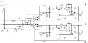
Errata:
1. The 1.2k and 820 resistors in the feedback amp divider were reversed. The 1.2k goes to + out and the 820 to - out.
2. The decoupling caps I have are 250V, not 100V. This makes little difference, but it is worth noting; I recommend 100V minimum for all caps in this design.
3. My output clamping diodes are 1N4002, not 1N4004; the 4002 is a 100V diode, 1A just like the 4004, so this makes little practical difference, but I'd recommend the 4002 as the minimum, since the 4001 is only good for 50PIV. Again, it makes little difference, but 100V minimum is the recommendation.
4. I added a 0.1uF decoupling cap to the base of the feedback amp transistor, Q3/Q7, to the negative rail. This is to provide dominant bypass, a required stability feature for this type of regulator.
My 10000uF 100V smoothing caps will arrive near the end of the week. I hope to be far enough along to know whether they are really worthwhile by then. They will also serve as a backup plan in case my regulation schemes fail utterly (unlikely, but the wise engineer makes contingency plans for everything. Remember the seven Ps).
Testing results:
Testing showed that the original current limit of 7.52-7.95A (at .65V to .85V Vbe for Q4/Q8) is insufficient for startup. I get motorboat oscillations in the power amplifier, showing that the output impedance is insufficient. I have upgraded to 10.12A, with a short load current of 1.44A, by increasing R3/R13 to 5.1k.
I also discovered high frequency oscillation of the current limit transistor, Q4/Q8, which I avoided by bypassing from emitter to collector with another 0.1uF 250V cap, and I'm delaying startup of the current limit by adding a 1uF cap to the negative rail to its base; this cap will also decouple even quite low-frequency oscillations in the sensitive base of this transistor. I have not yet determined whether another 0.1uF decoupling cap should be added to the base of Q1/Q5; I don't expect so, but I am prepared if it is necessary. This (1uF across R4/R12) is permissible to permit charging of capacitances on the amp board; the time constant is on the close order of 32ms. Over this time it should be impossible to draw sufficient current to destroy the 2N3055 pass transistors, even into a direct short to ground. The resistance of R5||R6/R14||R15 will prevent it, since there is build time for the transformer's magnetic field, and charging time constant across the input smoothing caps combined with the transformer internal resistance and the rectifier voltage drop and stray capacitance to consider as well.
Testing at 10A current limit, with the listed bypass and slow-limit caps in place, will commence this evening after work.
It is also worth noting that the preamp and chorus boards are taking their power from the positive rail of the power amp power; since a matched pair of 7815/7915 regulators is in use on the chorus board (where this power comes to them), it is my intent to take the input to this regulator pair from the positive input rail to the new regulator, rather than from its output, to ensure good balance between the two regulators, and to free the power amp board from having to deal with the consequences of events on these other boards other than their output. The draw is no more than 2A (limited by the capacities of the 7815 and 7915), and this should make little difference at the output, since line regulation is one of the strengths of this design.
ETA: I will also probably go get a pair of 25A rectifiers this evening; 8A is a little under what I really need, and the next they have is 25A.
Well, it worked, but when I was all done it dissipated too much power inside the chassis. No more dropouts, though, and no more hum.
But while I was poking around, I came across the capacitance multiplier- a much simpler circuit than the full-on regulator- which reduces ripple to managable (and even infinitesimal) levels without overstressing the pass transistors. The basic principle behind the circuit is to use the DC beta of a transistor to multiply the capacitance in a capacitive-input filter. From the point of view of a computer, the regulation would be unacceptable, but for a power amplifier, you frankly want as much of the voltage from your transformer and rectifiers as you can get, to reduce dissipation in the power supply, with the minimum ripple possible. You're not worried about either line or load regulation, beyond that which the transformer can provide; the regulation provided by the transformer is more than sufficient for an audio power amplifier.
What you get from this circuit is lots and lots of amperes, without excessive dissipation in the pass transistor, and with a minimal component count. The cost is that you don't have any more load or line regulation than the transformer can provide, but because that's more than enough regulation for a power amp, what you're doing is throwing away the parts you don't need.
I had a look at this, but I don't think I need that much sophistication in this design; I intend to go with something much more like Ron Elliot's design. Mr. Evil's design is, however, very interesting for the extreme efficiency it allows.
I'll design this circuit today and implement it; I expect I'll get noise specs about as good as from my regulator, and considerably less dissipation. When I have settled on a design, I'll publish it here.
I think this might be just what the OP was really looking for: excellent filtering, good-enough regulation, low parts count and therefore ease of understanding and low cost, as well as low possibility of failure either in the design or the implementation.
BTW, Andrew, you asked Mr. Evil how to foldback limit his design in the second thread on it, and I think I see an approach that should work; Mr. Evil might like to see it too. If one can put a normal current limit on it, one should be able to put a foldback limit on too, at the cost of higher parts count, and potential feedback effects that might need to be damped. Let me know if you'd like me to develop it a bit further.
I'll be interested to see how you get on with the Cap Mulitiplier, when speaking with Rod Elliot in some depth about it, he recommended against it's use in anything other than class-a amplifiers due to the wildly varying current demands making it pretty much as wasteful as a regulator.
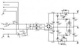
Here's a nice circuit diagram.
The minimum apparent capacitance in the filter is about 0.25 farad; at 10A, the minimum beta of the 2N3055 is 5, and at that same 10A and beta, it's drawing about 2A from the TIP31 or 32; at 2A, the beta of the TIP31 or 32 will be 15 minimum; that's a total beta of 75. Under normal operation, with both betas in the range of 50 to 70, it should be more like about 8 farads. This should be more than sufficient to calm my ripple problems. I've eschewed the dual RC filter of Mr. Elliot's original design; if it turns out to be an issue, I'll obtain some 470uF 100V caps and set up an RC filter.
This is fast, cheap, and highly performant. If closely enough matched transistors are available, the 6.8k and 5k resistors can be left out.
Any handy power transistors, provided they are relatively well matched-- and I don't mean anything like as well matched as they should be for a pushmipullu, same maker and part number should be fine-- should work fine for this circuit. The betas of power transistors are necessarily limited, so a Darlington pair is recommended; remember that beta often decreases with collector current, so be sure that the first transistor in the pair can handle all the current that will be required at the absolute minimum beta of the second transistor, at the maximum expected current. For the 2N3055, this absolute minimum beta is about 5, and the maximum current they can handle is 15A. I wouldn't put 15A through a 2N3055, YMMV but be careful you don't let the smoke out. I think 10A is probably pushing it, and if I expected that much load on a continuous basis, I'd be either using MOSFETs or parallelling the 2N3055s with base resistors at about 0R1, and at 5A or a bit more, like I expect, I'll be heatsinking them and making sure they're right in the main air path.
Note that putting MOSFETs into this circuit just about requires Mr. Evil's circuit in the thread I referenced earlier for reasonable performance.
At an absolute minimum beta of 5, I'll have to pump 1.666...A into the bases of the '3055s to get 10A out of their emitters (and pull 8.333...A into their collectors at the same time). Thus, the front transistors (TIP31/32s, MJE3055/2955s, whatever you happen to have on hand) must be able to handle this current. Be sure to check that the dissipation in the resistors that connect the bases of the front transistors can handle the current to the bases of the '3055s divided by the front transistors' minimum betas, too- in this case, that's a minimum beta of around 15, so you'll need 5W resistors (huh!?!? hope you were paying attention!) to be absolutely certain you can handle whatever this thing dishes out- it'll be drawing 111mA, and 220R dissipates 2.7W with that current. If you don't want to use 5W resistors, you can skimp by getting 150R 2W, 75R 1W, though I wouldn't go further down than that, with the predictable reduction in performance.
If you're not used to thinking about transistors, you might not see why you can use the NPN 2N3055 on the negative rail, but your Darlington front has to be a PNP. The reason is that for an NPN, Vbe must be positive to turn it on, whereas for a PNP, it must be negative. The relatively obvious substitution of an NPN for the front transistor won't work, because it will never turn on; if it ever did, it would work, but it can't start because there's no source.
I've breadboarded the negative circuit and tested it at 13.6V 1.36A (my test load was four 10R 25W resistors in series-parallel, for 10R and 100W, overkill perhaps but I don't really like 150C components floating around on my bench, plus they tend to scorch the test leads); I didn't want to take my amp apart again to get the 6700uF caps out, so I used an extra 3300uF cap for the input filter, C4. For the breadboard at this voltage and current, a 100R 1W resistor was fine for R2. I left out D2, since the load is static and totally resistive. I noted small defects in the output waveform coinciding with the top of the charging current waveform; they were about 0.2V. That's about 1.4% ripple, whereas with the same load directly connected to the 3300uF caps ripple is a hefty 20% or more. I suspect that the defects are due to the Vbes of the transistors. I'll bring it up to full voltage and run with nine of my test load resistors, three parallel groups of three in series, 10R 225W; at 4A 40V, dissipation will be 160W, and I have a bench fan to keep them relatively cool.
Attachments
I'm not so sure about that. He correctly points out in the article that you have to allow for both line and load variations with a regulator, which means that the voltage drop across the pass transistor can vary by 20% or more; this makes what otherwise would be a relatively simple circuit quite complex and increases the power handling requirements for the pass transistors enormously. That's the problem I ran into; if I left enough headroom to ensure that I would never brown out, I was dropping 6 to 8V across them or even more, and at 10A that's 80W or more apiece, and remember you have to double that. That's a lot of heat. That was the problem I ran into.richie00boy said:I'll be interested to see how you get on with the Cap Mulitiplier, when speaking with Rod Elliot in some depth about it, he recommended against it's use in anything other than class-a amplifiers due to the wildly varying current demands making it pretty much as wasteful as a regulator.
With just a cap multiplier, the voltage drop across the transistors is pretty much constant, and mostly dependent upon the Vbes of the transistors unless you fool with the bias point with R3/R5 (or R4/R6, depending on which side of the circuit you're looking at). This means that the most I'll ever drop will be about 3V; at 10A, that's only 30W, which a TO-3 can handle nicely with a small heatsink considering I'm using a fan, and considering I already need the fan to keep the drivers on the Lin amp cool.
From the point of view of bang-for-the-buck, those 150,000uF caps you guys are on about go for $50US or so each; 2N3055s are $1, TIP31/32s are $0.50US, the 220Rs are $2US, and the 6800uF 100V caps are the enormous sum of $5US. I'm figuring I can put this together for under $30 total, plus my time, instead of the $100 or more it would cost to get something that would perform worse and introduce not only the hazard of an exploding 150,000uF cap but a component that has a limited lifetime and costs like the dickens.
From a space point of view, I expect from my breadboard to have space left over, whereas I simply don't have enough room for two 150,000uF 100V caps, if I could even source them.
But where the rubber meets the road is once I get it tooled up and put it in there. Will the hum be reasonable, or perhaps even gone? Only time will tell. If it works for mine, it should work for anybody's.
I may wind up with a switcher yet. I hope not, but considering the time I've put in so far, it's looking more and more attractive. 😛
In case I wasn't clear earlier, a big thank you to Mr. Evil for both the nice MOSFET design and the commentary, both of which were most useful in evaluating this idea at the design phase (when it doesn't cost anything but skull sweat).
The cap multiplier doesn't offer any extra energy reserve, merely the same sort of (low) ripple that the much larger caps would have. In your case your amp seems very sensitive to sub-200Hz ripple (must be a shocking design IMO) so the cap multiplier might be what you're after.
Please keep us updated.
And whatever did happen to Mr Evil?
Please keep us updated.
And whatever did happen to Mr Evil?
An important point that I'd like to emphasize for the OP of this thread; you're entirely correct, richie00boy. This was why my first attempt had dropouts at high volume; I didn't have enough capacitor at the frontend of the power supply. No matter what you put in to handle ripple, you have to have enough capacitor at the frontend to supply all the current that the power amp will demand- you can't count on it being available from the transformer/rectifier at any given moment, because the wave might be down at zero. If you run out of electrons, your amp will drop out, and you'll get interesting dropouts that might even happen on, say, every third peak, causing various weird distortions of the waveform that you'll have a heck of a time diagnosing.richie00boy said:The cap multiplier doesn't offer any extra energy reserve,
My goal has never been to eliminate the capacitors-- just not require insanely huge and expensive ones.
The design goal was to offer competition to the Roland Jazz Chorus 120. They designed it to give 140W, just a bit more than the JC120; it has a bucket-brigade chorus, like the JC120, but with depth (that's how many repeats you get- technically speaking, this is actually a clean/effect mix control) and rate (that's how often the chorus sweeps per second) for each channel which the JC120 doesn't have; it has reverb on both channels which the JC120 doesn't have; and it costs less. You get what you pay for, and in this case, they took it out of the power supply and (clearly) the power amp design, as well as not providing vibrato. The power amp therefore isn't as good at rejecting noise as it might be, and although it does give really nice high end (which for a guitar is up in the 6-10kHz area), it's a little hissy and not quite as straight-ahead clean. At the time I bought it, considering the price/performance and the options the amp offered that the JC120 just didn't have, it was a good deal; and looking back, I'd buy it again, even knowing everything I know now. But if I can significantly improve it (and I already have done so), for reasonable effort and at a reasonable cost, then it's worth my time, and besides, I enjoy fooling around with stuff like this.richie00boy said:merely the same sort of (low) ripple that the much larger caps would have. In your case your amp seems very sensitive to sub-200Hz ripple (must be a shocking design IMO) so the cap multiplier might be what you're after.
If I got right down to it, and spent weeks and weeks on it, I bet I could find just what's wrong with the Lin amp, but you know what? Even after all the effort I've spent, I'm still ahead of the game. And even if I wind up with a switcher, I'll still be- there's no guarantee once I found the problem in the amp that there would be any good way to fix it; and if I did, it would probably be Frankensteined, with resistors and crap hanging out all over the place. Knowing as I do now that the bulk of the problem is the ripple, I can address it without taking that risk.
My design goal, therefore, is to
a) remove the noise,
b) without generating excessive heat,
c) for a reasonable cost,
d) in the available space,
e) without unreasonable effort.
So far, so good. I've shown that by reducing the ripple, I can eliminate the noise, and I've also "taste tested" it with a ripple-free power supply and shown that all else (heat, dropouts) aside, it really does sound significantly better in all volume regimes with reduced ripple. My last design even eliminated the dropouts, but at the expense of more heat than I'm happy with. As a final backup position before doing a switcher, I can always double-gang a pair of LM338s on each rail. But if I don't have to regulate it, why regulate it at the cost of the heat, and the extra component cost? If I can eliminate the ripple without regulating it, why not just do the minimum necessary? I think that's the question that Mr. Elliott (apologies for the earlier mispeling) was answering.
You bet.richie00boy said:Please keep us updated.
Hi,
the linked schematic by Mrevil is a full regulator, not an improved multiplier.
The multiplier can and does reduce the ripple but the transformer regulation will still allow the voltage to dip, but that's OK since it gives some SOAR protection to the output transistors.
The basic multiplier you posted shows 220r and 3.3mF which will reduce the ripple significantly,
However, you can reduce the RC time constant slightly and put in a cascaded RCRC smoother feeding the pass transistor with much improved ripple attenuation.
100r feeding 3.3mF then another 100r feeding a second C will respond a little quicker than 300r.
The problem you should try to avoid is the pass transistor becoming fully open (saturated) and the voltage falling on the supply side. The ripple dips then pass through the pass device and you have ripple on the output. A very stiff and/or slow base feed runs into this problem when feeding large changes in output current. It is the large changes in ClassAB that causes the ripple dip feedthrough. This does not happen in substantial or fully ClassA amps. The reason ClassA benefits from the multiplier is that the PSU is supplying substantial current to feed the large output Iq when zero or tiny input signal is present and this leads to ripple on the amplifier output or very large capacitors in the PSU smoothing section (roughly two to three times that usually used for ClassAB).
Bringing me, neatly, to your reference to 150mF 100V smoothing caps (where did that recommendation come from?).
The recommendation I put forward, gleaned from a number of knowledgable sources, is 2mF to 3mF per Apk of amplifier output.
Your 50W amplifier does not need 150mF which would imply an output capability of 50Apk to 75Apk into your normal load (impossible). and 100V caps are not required either.
What is the open circuit voltage of the amplifier PSU when mains supply voltage is at maximum? A 50W amplifer might just be able to work, safely, with 50V caps but I suspect they could go over voltage on worst case conditions. Therefore almost everyone will use 63V caps. These are cheap and small.
I have 10mF and 15mF 63V and they are only 35 diam by 60 long, probably not much different from the 6m8F fitted as standard.
Finally, many that have fitted multiplier PSUs say they do not sound as nice as the standard PSU. That one is down to listening and your priorities.
I'm not so sure- a regulator by definition regulates the voltage, which that circuit doesn't really do- IOW, if the line drops, the output drops, and if the load goes up, then the output from the transformer will cause the line to drop. So it really has no better line or load regulation than the transformer already did. However, it should and according to Mr. Evil's testing does drastically reduce ripple. OTOH, it also doesn't really appear to be a capacitive multiplier any more either. I think I'd let Mr. Evil dub it.AndrewT said:Hi,
the linked schematic by Mrevil is a full regulator, not an improved multiplier.
That's my thinking, too. And I'll go one step farther: since the transformer's regulation when added to the existing 6.7mF smoothing caps appears to be sufficient in the designers' minds, and since I see no serious defect in the amp at high output as it stands (the hum is pretty much constant, and when the amp is putting out a lot it's overwhelmed), I have every confidence that it will still be sufficient after I am done.AndrewT said:The multiplier can and does reduce the ripple but the transformer regulation will still allow the voltage to dip, but that's OK since it gives some SOAR protection to the output transistors.
I am in fact running my breadboard at the moment with a 100R 2W, having been too lazy and busy to get out and get the 220R 5W I should really be using. Now it appears that I shouldn't really be using that; how serendipitous. Glad I didn't spend any money on it.AndrewT said:The basic multiplier you posted shows 220r and 3.3mF which will reduce the ripple significantly,
However, you can reduce the RC time constant slightly and put in a cascaded RCRC smoother feeding the pass transistor with much improved ripple attenuation.
100r feeding 3.3mF then another 100r feeding a second C will respond a little quicker than 300r.
I've verified so far that it definitely smooths the ripple; also that it will handle 40V 4A forever. The heating is far less.
You are correct; in fact, I see 0.2V defects about 0.8ms long that coincide with the bottom of the voltage ramp. This is a drastic reduction in ripple compared to the input, but nevertheless irritating, and I suspect I'd be able to hear it, although I'm not certain that it wouldn't be cancelled in the diff amp. I should mention that this was during my initial testing at about 15V input and 13.6V output; upon increasing the input to some 47Vpeak, the output at 4A went to 37V, and these defects increased to some 0.4V, though they are no longer than they were.AndrewT said:The problem you should try to avoid is the pass transistor becoming fully open (saturated) and the voltage falling on the supply side. The ripple dips then pass through the pass device and you have ripple on the output.
I'm not so sure of that; my test load at 40V 4A was nine 10R 25W wirewound resistors, three by three, for a total resistance of 10R 225W. I saw these defects under this steady load. However, I do agree that too stiff a base drive on the front transistor of the Darlington pair may be to blame; and I note that there was no discernable change at any setting of the 5K pot, although I did not measure the voltage across the pair nor the voltage at the base of the front transistor. I will probably do this measurement today; the other possibility that occurs to me is that my smoothing caps may be insufficient, since I am using 3300uF rather than the 6700uF, because as I said I didn't want to take the amp apart until I had a workable circuit that could clearly handle the load and that had good ripple characteristics under steady heavy load. I am close enough now that I will almost certainly lug the amp downstairs today and pull out the 6700uF caps and run a full test. If the 6700uF caps don't fix it, I'll start reducing the base drive. But because the resistor to the rail is low, and must remain so to give good filtering, I'll have to be very careful not to go too low and burn the resistors.AndrewT said:A very stiff and/or slow base feed runs into this problem when feeding large changes in output current. It is the large changes in ClassAB that causes the ripple dip feedthrough.
I also have to point out that weakening the base drive will tend to bring the main pass transistor out of saturation and into the active region, at which point it might be considered to begin to regulate rather than merely amplifying the capacitance; but we'll see about that, it depends I suppose as much upon one's opinion as to the meaning of "regulation" as it does upon the operation of the circuit.
I can see the constant load, but I have to point out that if it's sufficient to handle a constant load at the highest current the amp is ever to draw, it should be capable of handling whatever variation occurs below that point unless there is a feedback path that causes modulation across the pass transistor, and one of the nice things about this circuit is that such paths are severely restricted. The base of the Darlington pair is connected to ground (through the biasing resistors) and the input rail, not to the output rail; this is part of what distinguishes this circuit from a true regulator, because it does not measure or act upon the output voltage which a regulator must necessarily do.AndrewT said:This does not happen in substantial or fully ClassA amps. The reason ClassA benefits from the multiplier is that the PSU is supplying substantial current to feed the large output Iq when zero or tiny input signal is present and this leads to ripple on the amplifier output or very large capacitors in the PSU smoothing section (roughly two to three times that usually used for ClassAB).
I believe I was clear when I said it that I was exaggerating and aware of doing so.AndrewT said:Bringing me, neatly, to your reference to 150mF 100V smoothing caps (where did that recommendation come from?).
I believe you are correct; I estimate the requirements as some 200W/40V=5A, and the correct capacitance therefore at some 10-15mF. Because I had not searched all the references, I was not aware that such caps were available at much lower prices than I expected.AndrewT said:The recommendation I put forward, gleaned from a number of knowledgable sources, is 2mF to 3mF per Apk of amplifier output.
Your 50W amplifier does not need 150mF which would imply an output capability of 50Apk to 75Apk into your normal load (impossible).
My experience is that overrating power supply caps is always a good idea. 200% voltage ratings are not an uncommon recommendation for homebrew gear, and the ARRL Guide is a relatively prestigious source that makes this recommendation, although this is certainly not the industry practice, which is very much more like the barest minimum that will work. I've spoken of industry practices to you before, though not in an open forum.AndrewT said:and 100V caps are not required either.
I might go with 63V caps, if the size of 100V is prohibitive- the cost certainly isn't, though I thought it was. I'll point out that the original equipment is 50V caps.AndrewT said:What is the open circuit voltage of the amplifier PSU when mains supply voltage is at maximum? A 50W amplifer might just be able to work, safely, with 50V caps but I suspect they could go over voltage on worst case conditions. Therefore almost everyone will use 63V caps.
Cheap I'll agree with, small I'm not so sure about. The space in my enclosure is quite limited.AndrewT said:These are cheap and small.
Haven't measured them, nor checked the measurements of my proposed replacements. I might do that today while I have them out.AndrewT said:I have 10mF and 15mF 63V and they are only 35 diam by 60 long, probably not much different from the 6m8F fitted as standard.
We'll see. I intend to be quite picky, not that I'm not already. That hum is really irritating. Particularly when I'm recording ambient (as opposed to direct input, which is quiet), or playing live.AndrewT said:Finally, many that have fitted multiplier PSUs say they do not sound as nice as the standard PSU. That one is down to listening and your priorities.
Thank you for your thoughts. They are a help in evaluating my observations and deciding which paths are most likely to be fruitful. And I always have the twin regulator approach in my back pocket if all else fails.
That was it!
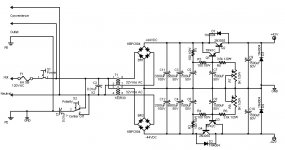
It works great. Sounds like a million bucks. No hum, no buzz, no dropouts, no heat.
I redid a couple things- I had some 3300uF 50V caps lying around, as well as the two 100V ones I had, so I beefed up the input smoothing network to 6800+3300uF in parallel. This obviates buying 10000uF caps. I also decided to go with 1500uF caps in the base drive network, and used Andrew's suggestion of two filters, each an R in series and a C in parallel, 100R and 1500uF. I changed the 3.3k resistor to 3.6k, and moved my 3300uF caps that I was using in the base drive to the output. And at the last moment I decided to put a pair of 1N4004s on the output, just to clamp everything where it's supposed to be... JUST IN CASE.
The 0.2V glitches are just plain gone. I don't know if reducing the base drive did that, or increasing the smoothing network, but whichever, it works fine.
I'll tell you something else, too: I was using those 3300uF caps in parallel with the 6800uF in the amp already- yes, kids, I had 10100uF on each rail, and it was still buzzing like a beehive. So much for beefing up the filter caps. I'd forgotten I left them in there. They sure didn't do much good. But slap that cap multiplier in there, and Bob's your uncle!
This is IMHO the right way to go for the power supply for a power amp- at least a Lin amp. I played a little, and it sounds GREAT- of course, I can't crank it, it's midnight here and the neighbors would run me out of town on a rail, but tomorrow... 😀 😀 😀
Here's the circuit. Let me know if there are questions.
ETA: and before I forget, a big THANK YOU to everyone who made suggestions, and with Andrew for putting up with my cranky old ***. 😀 Thanks guys, I really appreciate it.
Attachments
- Status
- Not open for further replies.
- Home
- Amplifiers
- Power Supplies
- Power Supply Design for a solid state amplifier