OK, I'm just about done analyzing a 2-rail supply with full protection, using LM338s. It's a modification of the National "floating regulator" application note, with a 5.1V zener to hold the input-to-output voltage across the regulator to under that value, a 2N3055 to block the input voltage, and a 2N3904 to do foldback limiting on the base of the '3055. I've used a pair of 1-ohm 10W resistors, Radio Shack $1.95 each, for the current sensors.
The '3055 dissipates about 20W max; the zener and '3904 are protected by a 10k resistor, limiting current to about 4.7mA total between them. The only thing I'm having trouble with is there might not be enough current to give the output I want; with a DC Beta of about 35, I might have to Darlington the '3055 to get enough current through it. I'm lookin into it. I'll post when I'm done. Keep yer eyes open.
The '3055 dissipates about 20W max; the zener and '3904 are protected by a 10k resistor, limiting current to about 4.7mA total between them. The only thing I'm having trouble with is there might not be enough current to give the output I want; with a DC Beta of about 35, I might have to Darlington the '3055 to get enough current through it. I'm lookin into it. I'll post when I'm done. Keep yer eyes open.
OK, here's two of 'em. The second one is a pair of LM338s with appropriate protective circuitry. When I was done with the design, I realized I could get about the same performance and a smaller size with a discrete supply, and since most of the work to do the discrete supply was already done protecting the '338s, I did that too. The one in this post is the discrete design.
I invite analysis and commentary. I intend to breadboard the '338 design; the discrete design should be breadboarded carefully and operated with caution until its operating parameters are clear. I'll include my analyses following these two posts, and I'll post breadboard results when I have them. The transformer has arrived, but today is band practice so it might be a few days.
I invite analysis and commentary. I intend to breadboard the '338 design; the discrete design should be breadboarded carefully and operated with caution until its operating parameters are clear. I'll include my analyses following these two posts, and I'll post breadboard results when I have them. The transformer has arrived, but today is band practice so it might be a few days.
Attachments

OK, now here's how they work. First, the discrete one- it makes the LM338-based one easier to explain.
Q1 and Q2 pass transistors are a darlinton pair of MJE3055/2N3055, basically the same transistor but a little less beefy and a little more gainy in the MJE line- it's a TO-220 instead of a TO-3 like the 2N3055. The darlington pair configuration guarantees enough gain to make sure that there is solid current flow in the main circuit. The 5.1V zener was chosen because in this value range, zeners have a very low temperature coefficient, and inherently low bulk resistance. This means that the 5.1V breakdown voltage varies almost not at all with either current or temperature. Q3 is the feedback amplifier, and R7, R8, and R9 are its voltage divider. Because this is closed-loop voltage gain, we do not need to consider the DC Betas of the transistors until we calculate to be certain there is sufficient current, and that the 2N3904s won't burn; the voltage gain is
A = 1/B
Where,
A is the closed loop gain, and
B is the feedback fraction.
The feedback fraction is just
B = (R9 + part of R8)/(R9 + R8 + R7)
For reference, this should be calculated for R9+R8/(R9+R8+R7)
and for R9/(R9 + R8 + R7) to show the limits of the adjustment. But we won't use this equation; we just need to get the closed loop gain, so let's solve for that.
Rearranging,
A = ((R7 + part of R8)/(R9 + the other part of R8)) + 1
And as above, this should be done for R7/(R8+ R9) and (R7 + R8)/R9, to get the limits. This gives us a lower limit of 1.132258064516129032258064516129 and an upper limit of 5.85.
Now, the output voltage is
Vo = (Vz + Vbe)/B
Where,
Vo is output voltage,
Vz is the zener diode breakdown threshold voltage, 5.1V, and
Vbe is the base-to-emitter voltage of Q3, about 0.65V according to the data sheet, with a max value of 0.85V. But there is an easier way to do this:
Vo = A(Vz + Vbe)
So we have to calculate for A = 1.13 and A = 5.85, and Vbe = 0.65V and 0.85V. The four answers are:
6.5104838709677419354838709677419V @ Vbe = 0.65V and the pot turned all the way up,
6.7369354838709677419354838709677V @ Vbe = 0.85V and the pot turned all the way up,
33.6375V @ Vbe = 0.65V and the pot turned all the way down, and
34.8075V @ Vbe = 0.85V and the pot turned all the way down.
Right off the bat, I got a problem, and I know where it came from. When I did the original calculations, I used Vbe = 1.5V + 1.8V, automatically using the darlington drop and the max Vbes from the darlington pair. So R9 is too big to get high enough. We'll have to bump it up.
We'll shoot for A of 8.7, to get us just over 50V; with Vin at 47V, we can't ever actually reach this, of course, but it ensures that we can get as high as possible. There is a warning to be aware of here, though; if you push the regulator too far up, you'll brown out, just like 3-terminal regulators do. I'll show you how to calculate the brownout voltage shortly.
This means that (R7+R8)/R9 should be as close as possible to 7.7 (remember you have to add one!). The 5k pot is pretty standard, I use the little ones with high stability. So if we use a 1.3k for R7, and an 820 for R9, that will give us 49.93V at the top, and 7.03V at the bottom.
And another warning: if you run this supply at 7.03V, don't be expecting to get 5A out of it- that would be 40V across the pass transistor, which would get you 200W dissipation out of a transistor that only can handle 115W, and that's assuming a perfect heatsink!
Clearly, for the voltage levels desired by the original poster, a yet higher value for R7 and perhaps a somewhat lower value for R9 will be needed; with the demonstration above, it should be little trouble to get what you need using this regulator. If you want me to check your results, post them, and be detailed: show me your work. If you're confident enough to press on on your own, more power to you (so to speak. 😀 )
OK, now let's talk about another important feature of this circuit. It uses foldback current limiting, implemented using R5 and R6 as the sense resistor, R3 and R4 as the voltage divider, and Q4 to control the base voltage of Q1 and implement the foldback. The current limit in this scheme (this is standard for foldback limiting, so pay attention) is
Isl = Vbe/K(R5||R6)
Where,
Isl is the current into a shorted load,
Vbe is the base-to-emitter voltage of our 2N3904, 0.65 to 0.85 volts,
K is the feedback fraction of R3 and R4, that is, R4/(R3+R4), and
(R5||R6) is the value of the parallel pair of R5 and R6, that is, 0.5 ohms since they are both 1 ohm resistors.
Note carefully that these are 10W resistors, for a total dissipation of 20W between them. If our current limit is to be 5A, these resistors will drop 2.5V; this means that they will dissipate 12.5W, or 6.25W each. The maximum current limit we can implement with them is therefore
(20W/0.5ohm)^.5, or just over 6A. For this circuit,
Isl = (.065V/(((47k/(47k + 3.6k))x(0.5ohm))) = 1.399A. You'll notice you've come out very close to my targeted value of 1.4A. At this value, with input of 47V and output of 40V, the pass transistor will dissipate 7V x 1.4A = 9.8W, eminently reasonable.
Now under normal operating conditions, the total current will be:
Imax = Isl + (Vo(1 - K)/K(R5||R6)
Where:
Imax is the maximum load current.
Thus we see that we can get
Imax = 1.4A + (40V(1-(47k/(47k + 3.6k))))/((47k/(47k + 3.6k))0.5ohm) = 6.13A. This is why this type of limiting is called "foldback;" the current limit decreases as the load increases beyond the programmed current limit. In this case, the programmed current limit is 6.13A, and if we are dropping 7V across the pass transistor, then it is dissipating 42.89W. This is a heavy load, but it is well within the capabilities of the 70V, 15A, 115W TO-3 cased 2N3055, if it is properly heatsinked; most likely, if this amount of current is to be drawn for any length of time, or on a regular basis, it would be best to use a fan to cool the heatsink and transistor. But at 4A, we dissipate a much more reasonable 28W, which we can expect to dissipate without a fan and with a reasonably sized (and priced!) heatsink.
Now for the remainder of the supply's parts. R1 limits the current through the zener to 20.95mA, eminently reasonable for this 1W device, which dissipates 107mW under this load. R2 limits the current to Q3 to the same level, resulting in an even lighter load under normal conditions, since the transistor operates in the active region, not at the rail. And even at the rail, 107mW is by no means excessive for this 250mW device. R2 also provides current to the base of Q1, forward biasing the BE junction and taking this transistor into the active region; with a minimum gain of some 25-30 under its light loading, and with an equal minimum gain of 25-30 in Q2, we see that as little as 1mA results in the flow of a minimum of some 625mA, and with the more substantial current levels available of 10mA, we can send 6.25A out; this is at our current limit, so there will be no problem maintaining the setpoint voltage, provided we don't brown the regulator out.
The functions of the filter caps are obvious enough that I won't bother unless asked. The 1N4004 diodes are to clamp the voltages positive; this prevents oscillations at startup from resulting in a blown supply, ensuring stability.
The negative half, of course, uses the complements of the '3904, MJE3055, and 2N3055, and works in precisely the complementary way. Because the output voltage is controlled by the closed-loop gain, which is not determined by the DC betas of the transistors, but by the ratio of R16/(R16+R17+R18) and so forth, we do not need to worry about the fact that the 2N2955 has a rather higher DC beta than the 2N3055; it just means that the MJE2955 won't have to work quite as hard as the MJE3055 does (and the MJE3055 isn't working very hard).
Comments welcome.
ETA: Oh yeah, brownout.
Well, you got two Vbe drops across the darlington pair, and your drop across the sense resistors; like I said above, the max drops are 1.5V and 1.8V, so that's 3.3V, and at 6.13A you'll be dropping 3.065V across the sense resistors, so that's 6.3065V maximum brownout, and more like 1.4V minimum. Our 7V looks like it leaves us a nice margin.
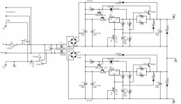
OK, now the '338-based one.
The foldback limiting works the same way, and you'll note it uses the same resistors and transistor as well.
The 2N3055 stands off the voltage in excess of 5.1V above the output voltage. Note that this means that the current capacity of the transistor is compromised if the output is a lot below the input- just as in the discrete regulator. The zener diode sets the voltage from the output of the regulator chip to the base of the MJE3055; the MJE3055 drops 0.6 to 1.8V, and the 2N3055 drops a further 0.7 to 1.5V, so between 1.3 and 3.3V of the 5.1V the zener makes gets dropped across them, leaving 3.8 to 1.8V; this is below the regulator's brownout, but note that the higher Vbe(on) occurs when Vce is high- these are the worst conditions. Under more normal conditions, like the constant intended operating conditions of this regulator, this should not be a problem, however, it must be carefully breadboarded and load tested to ensure that there is sufficient headroom. If there is not, a zener rated at 1 to 1.5V more should do the trick.
The foldback limiter circuit is required to protect the 2N3055 from an output short, which would otherwise overload and quickly destroy it. The current limit on the chip would not limit enough to prevent this. The 2N3055 protects the LM338 from higher voltages than it is rated for, and the transistor can handle 60V, and pass 15A, and dissipate 115W. The darlington pair again increases the current amplification of the transistor to allow sufficient current to pass. The protection diodes protect the LM338 from cischarges of C5 and C6 as in the standard circuit.
The main advantage of this circuit over the discrete regulator is that it will be much quieter; perhaps as much as 15dB, or even more. I'll get into the ripple calculations, and show a few other things this circuit does that the discrete one does not, later.
Hi,
can you move your foldback limiting to upstream of the regulator?
Otherwise the 3V (@Iout=6Apk) drop across the sense resistors ruins the regulation. i.e. the output voltage modulates with load demand.
What is the purpose of the polarity switch S2?
Cap C2 is X rated and cap C1, usually two of them, is Y rated
if you are going to go to all this work -- why not use a decent error amp and reference instead of the quite (very) inadequate LM338 -- take a look at the impedance plot of this device --
...and that's why I put it out for review. Nice suggestion, Andrew. I'll do that. There's no reason not to, and good reason to do it.AndrewT said:Hi,
can you move your foldback limiting to upstream of the regulator?
Otherwise the 3V (@Iout=6Apk) drop across the sense resistors ruins the regulation. i.e. the output voltage modulates with load demand.
Since I intend to use this in my amp, I included their power wiring; I didn't question it other than to briefly mentally note what I'm about to say, but since you ask, my assumption based on what I see it doing is that it's intended to cancel noise on hot or neutral, or else decouple ground from either if it's off. I've never been able to hear a difference no matter how it's set, and as a result I generally leave it off in the center position. I suspect this is as close to a ground lift as they could safely come. I should have mentioned that everything left of the transformer is how the amp is wired from the factory. Thanks for pointing this out. I will repost without this shortly.AndrewT said:What is the purpose of the polarity switch S2?
Since it seems odd to you as well, perhaps you begin to see why I question every detail of their design, with particular attention to the way they have dealt with grounding.
Correct, and I should have noted it. For those not familiar with this rating system, all capacitors on the power line side of a transformer, that is, for those who use the British terminology, the "mains" side, must be specially rated to handle power disturbances, and specially constructed so as not to expose the equipment or through it the user to dangerous line voltages. For this application, Class X2 should normally be sufficient for C2, although X1 would be more effective, and in fact X2 is installed; since I use an Isobar surge suppressor, I didn't see a need to increase to the higher surge rating of 4kV that X1 provides. Technically, X1 is considered necessary by the IEC in all applications where the capacitor is upstream (on the line or mains side) of the fuse, so again, X2 is what is required here.AndrewT said:Cap C2 is X rated and cap C1, usually two of them, is Y rated
There is only one C1 because they provide a switch to use it for hot, neutral, or neither. It would, as Andrew points out, be more normal to provide two of them, one to hot and one to neutral.
The longer I look at it, the more convinced I become that you're right. That's partly why I did the discrete design, in order to have a starting point for investigation of such options. I may well take your advice, although I have to say that I'm not sure it's worth putting a $200 power supply into my $5 amplifier (I exaggerate, but you get the idea, I'm sure).jackinnj said:if you are going to go to all this work -- why not use a decent error amp and reference instead of the quite (very) inadequate LM338 -- take a look at the impedance plot of this device --
I also have to point out that as the design becomes more complex, it becomes more and more out of the reach of a beginner, which is at least partially what this thread is about; that's why I did the detailed analysis of the discrete regulator, in addition to the fact that the design as given doesn't give quite the performance that the OP indicated they need; this last because the values are appropriate to my application rather than the OP's.
But of course, what's really interesting is how it will behave when I put it to the test. The 'scope tells all (at least if you know how to make it do so). 😀
I'll also point out that in an amplifier that's designed to handle at least some noise, as all Lin amps appear to me to be by use of a diff amp at their front end, and when both cost and construction difficulty are considerations, bootstrapping a design from a usable if not necessarily ideally designed component might perhaps be better than attempting a fully featured and therefore highly complex design, and in addition, in this application, you must admit that ANY (competent) regulation is better than none. To put it another way, while it may not be perfect, it should be more than adequate and it certainly is better than inadequate simple capacitive filtering and smoothing alone.
You yourself pointed out that it wasn't short-load protected; so fine, now it's short-load protected. I'll point out again that at this juncture, due to the complexity of the design necessary to protect it, the value and complexity of power supply may now be approaching that of the amplifier. While I'm sure that this seems appropriate where the absolute acme of performance is desired, I'll point out that if an output transistor goes short, what happens to the $1.98 voltage regulator may well be a matter of little concern to the user, and I'll also point out that someone suggested using a 6A fastblow fuse and this may well be seeming a more and more attractive as the design becomes more and more complex. While the $1.98 regulator may blow and protect the $0.50 fuse in this case, it will be of little consequence compared to the destruction of the $10 worth of output transistors that caused it.
I'm kind of waiting for the OP to respond and let me know whether s/he was able to make any sense of it. If so, I'm prepared to respond as appropriate to various levels of knowledge; I find that not only is it more polite to assume a reasonable level of skill, and let them tell me if I'm going over their heads, but it's also more helpful in terms of folks actually learning some ideas they can use later, rather than just another cookbook design. Speak up. Is this useful, or are you completely lost at sea? Don't be embarrassed, I spent a long time and a lot of money learning this stuff, and an even longer time (although the money generally went the other way 😀 ) using it, and if you're a beginner, you're doing well to even ask the question in the first place.
Hi Shredly,
your value judement is right.
So back to my earlier point.
The hum is almost certainly due to an earthing/grounding loop/wiring error. Inserting a regulator is unlikely to be the solution that is required.
Any decent amplifier should have sufficient ripple rejection to give a quiet output.
Just compare all the other ClassAB threads running at the moment that complement the quietness of their amps.
richie00boy said:I agree with Andrew. Regs might help a little, but you will be masking the underlying problem.
and as I said at the outset -- you burn watts that could otherwise be turned into music --
two identical amplifiers -- two identical setups -- ceteris paribus the one which is tuned 0.1 dB louder will sound "better"
and speaking of $5 amps -- nothing warms the heart more than an inexpensive amp which sounds good --
Well, you've seen the schematic, and according to your lights, the ground is wired the way you say it should be. It's a circuit board, it's kind of hard to wire it incorrectly. I've described the grounding in detail.AndrewT said:Hi Shredly,
The hum is almost certainly due to an earthing/grounding loop/wiring error. Inserting a regulator is unlikely to be the solution that is required.
As I told you in the other thread, there's no question of it being anything outside the power amp; it hums when shorting plugs are plugged into its input, and for that matter when the inputs are shorted on the board, to any of the several available grounds, including the one that goes to the jacks. There isn't any place except on the circuit board itself for the hum to come from; and if there's a flaw on there, it's a design flaw. Yet, it's done with a "star ground" just the way you say it should be. So fine, where's the "ground loop" or "wiring error" or "grounding error?" According to your description of how the grounds are supposed to be arranged, there isn't any.
You still haven't answered how it can be a ground loop in something outside the amp board when the inputs are shorted. Let me repeat that yet again: there is no difference in the hum at the output when the inputs are shorted, and no difference when all the other boards in the amplifier are disconnected completely. There's nothing left inside the chassis except the amplifier board and the transformer and 120V wiring. The inputs are shorted. And still it hums. You have the schematic in front of you. You nor anyone else can point to a flaw in the design. Yet still it hums. The grounds are arranged precisely as you claim they should be, going separately to a star grounding point. Yet still it hums.
And if it's some faulty component in the power amp, the exact same thing is wrong with both of 'em- remember, this is stereo, there are two identical amps here.
And that's how it's been since the day I bought it. And I'll tell you something else: most guitar amps made back then hummed just like this one does. It's not excessive, by the standards of the day. But it's there, and it's objectionable to me.
See, this is frustrating. The schematic is right in front of you, and the grounding is done just the way you say it should be. So where's the problem?AndrewT said:Any decent amplifier should have sufficient ripple rejection to give a quiet output.
Just compare all the other ClassAB threads running at the moment that complement the quietness of their amps.
I know where the problem is, I can see it with my 'scope. It's on the rails. They have 5V of ripple on them. They didn't have to be any better than that back then to be no worse than the competition. The designers hoped to beat the competition on features, and IMO they did so. It has a really nice sounding chorus, and it has a really nice reverb, and it has a dirty and a clean preamp channel each with a 3-band EQ, and the clean channel has a treble boost. You put two 4-ohm 2x12" cabinets on this puppy and crank the input up, and it will blow the windows out of your house; it's loud enough to be painful standing in front of it in the open air within 10 feet, plenty for any gig you don't need a kW PA system for. The S/N ratio at that point is probably 90dB, and perhaps better than that, and that's pretty quiet. That's not the point. The point is, it hums when it's turned on.
I'm gonna fix it. If you think there's some kind of design problem with the amplifier, point it out; everything you need is right in front of you. Want me to take some measurements? Sure, name them. Got a suggestion? I'm willing to listen. But at this point, what I hear is a mantra, not careful consideration of what you're looking at and a direction for troubleshooting. I have a direction for troubleshooting, and I'm gonna pursue it, unless I get a suggestion that makes some sense.
Again, WHAT "underlying problem?" The schematic is right there, posted on this board. A complete description of the grounding arrangement has already been made. Nobody's pointing out any problems; all I keep hearing is, "it's wrong," without any indication of WHAT is wrong. Someone suggested there might be a problem with the zener diode transmitting noise into the current source for the diff amp. I bypassed the zener diode three different ways, and the noise was unchanged. It's not the zener diode.richie00boy said:I agree with Andrew. Regs might help a little, but you will be masking the underlying problem.
I can see what's wrong; its using an unregulated supply because the manufacturer was too cheap to put in a regulated one. And I'm gonna prove it. What this looks like to me is a means of covering your *** when it works.
Again: if there's something wrong with the design of the amplifier, POINT TO IT. The schematic is available on another thread on this board, and a complete description of the grounding as well. I'll point out yet again, because we seem to be losing sight of the fact, that this is a commercial product; that it has always behaved as it does now; that the hum happens when the inputs are shorted to ground on the board; and that we're not talking about excessive hum, but about objectionable hum. IMO, power amplifiers should be seen and not heard when there is no input.
And one more time for the stragglers, Naim seem to think that regulated power supplies are just fine for their amps. I agree with them.
So what? It ain't like I'm runnin it off a battery, man.jackinnj said:
and as I said at the outset -- you burn watts that could otherwise be turned into music --
Ummm, IIRC you can get 15A out of a wall plug. At 120V. That's 1800W. We're nowhere near that, either in my amp or in the one the OP described; we're talking about 200W at the outside. So what was the limitation you had in mind again?jackinnj said:two identical amplifiers -- two identical setups -- ceteris paribus the one which is tuned 0.1 dB louder will sound "better"
And nothing is worse than an otherwise excellent amplifier that hums when you turn it on.jackinnj said:and speaking of $5 amps -- nothing warms the heart more than an inexpensive amp which sounds good --
Sorry to see this is causing you some distress. Sometimes it's only when you have the amp in front of you that you can click what the problem is. Unfortunately the logistics of that mean preclude much further comment on that basis from myself.
Forgive me for not reading the thread again, but did you find whether the hum is 60Hz or 120Hz?
I think you've already got it now, but zener diodes or other inherently 'noisy' components don't hum, they hiss. Hum comes from coupling or grounding issues.
Have you 'scoped the power rails?
Forgive me for not reading the thread again, but did you find whether the hum is 60Hz or 120Hz?
I think you've already got it now, but zener diodes or other inherently 'noisy' components don't hum, they hiss. Hum comes from coupling or grounding issues.
Have you 'scoped the power rails?
It's 120Hz, just below B on the second fret of the A string on a concert-tuned guitar, plus several harmonics , the most prominent of which is at 240Hz, according to my spectrum analyzer. Most musicians erroneously call that "60Hz hum," because they don't bother to know what frequencies their instruments make. It's exactly the same hum I've ever heard from any piece of equipment that has a lousy power supply in it, or uses one of those cruddy wall warts, or when the ground is broken in an instrument cable. Exactly the same hum I've fixed scores of times by putting in a regulator, or replacing the wall wart with a proper regulated power supply; bigger caps always make it quieter, but a regulator makes it GO AWAY, at least as much as one can in a world full of electric lights.richie00boy said:Forgive me for not reading the thread again, but did you find whether the hum is 60Hz or 120Hz?
And from cheap power supplies.richie00boy said:I think you've already got it now, but zener diodes or other inherently 'noisy' components don't hum, they hiss. Hum comes from coupling or grounding issues.
Yes. They have a few V of ripple on them, just as the theoretical calculations say a 40V full-wave rectifier with a 6700uF smoothing cap should have with a demand around what the amp is drawing.richie00boy said:Have you 'scoped the power rails?
OK I was just wondering about the possibility of a failing PSU cap. With 120Hz hum and strong 2nd harmonic it's not likely to be induced hum (would be 60Hz) from wiring.
Hi,
can you confirm that you have 5Vpp of ripple on the supply rails when the input is shorted and speaker/load connected?
I would expect only a few tens of mV in this condition.
can you confirm that you have 5Vpp of ripple on the supply rails when the input is shorted and speaker/load connected?
I would expect only a few tens of mV in this condition.
- Status
- Not open for further replies.
- Home
- Amplifiers
- Power Supplies
- Power Supply Design for a solid state amplifier