I thought about building a follower, but with a little twist- run two followers off of each side of a differential pair (such as the zen balanced line stage) and do away with the output cap. I had a schematic going one time that was completely direct coupled and used X feedback on the front end. I opted to build an Aleph X instead.
Do not be too patient with no cap at the output, since with the modulated Aleph current source we have the PS electrolytics in the signal path. It is tested and proofed.
FQAF44N08 are no more available ?
Hello, Andrea
I have got them locally in Tashkent (20 pcs.) for approx 3,5USD per piece.
Thanks for an inspiration I have got from your schematics.
ok, but I am sure these are better than IRF
Have you seen my new Hybrid design with Circlotron output ?
Have you seen my new Hybrid design with Circlotron output ?
ok, but I am sure these are better than IRF
Have you seen my new Hybrid design with Circlotron output ?
Now I am inspired by an idea of High Current Follower, I need to listen how will it sound.
The Circlotron you are mentioning, does it have constant current consumption from PS under signal?
In this case I would like good shunt PS for both sides, and this would kill economy and efficiency of the original circlotron. I wonder, why nobody reported 6-8A Follower still? It would fit any kind of speakers. As for possible sound, you could guess about it better than me.
😕Anyway, within a DIY it would be interesting to try. I guess this complete schematics should be good sounding.
bias regulation???
😕
bias regulation???
Hello, megatron78, welcome to the forum.
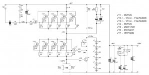
Schematics in the post#41 , as well as the original Follower schematics, observes one major rule - current consumtion from power supply is fixed by constant current source composed of VT3...VT6, while active "transistor" VT1-VT2 shares this fixed current with the load, at any time moment under signal.
This gives crucial sound advantages of this approach compared to alternative schematics. Disadvantages - low efficiency and big heat sinks.
Anyway, within a DIY it would be interesting to try. I guess this complete schematics should be good sounding.
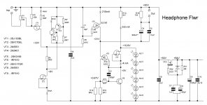
Intuitively I prefer the topology used by the Headphone Follower using K2199 and IRF610. How much wattage can be had from that small amp by replacing or paralleling K2199/IRF610?
Attachments
Last edited:
Intuitively I prefer the topology used by the Headphone Follower using K2199 and IRF610. How much wattage can be had from that small amp by replacing or paralleling K2199/IRF610?
Hello, Jay
I estimate possible wattage of this (with more idle current) K2199 based schematics, as 2W per channel, and 4W with the paralleled pair of K2199 (10W of heat is dissipated by each K2199).
What is interesting, just now I am playing with modified headphone schematics, with russian KP907A as an output active transistor (also 1...2W of output power, could fit sensitive full range speakers). Compared to K2199, the KP907A is more linear and has order of magnitude smaller Ciss, but rather low transcondustance (0,2S). I use some NFB in this case, in order to bring Zout below 1 Ohms range.
Thanks Vladimir,
What is the real reason you didn't use the circuit for a bigger 2-stage amplifier?
I will build a IRF510 version of this to find out.
What is the real reason you didn't use the circuit for a bigger 2-stage amplifier?
I will build a IRF510 version of this to find out.
Thanks Vladimir,
What is the real reason you didn't use the circuit for a bigger 2-stage amplifier?
I will build a IRF510 version of this to find out.
Actually I attached the output follower stage to this schematics, like here
http://www.diyaudio.com/forums/solid-state/189044-integrated-no-nfb-son-follower.html#post2572569
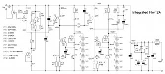
With this two-stage approach, it is difficult to get small output impedance. Even with IRF510 you will get something around 1 Ohm. If one would use more powerful transistor with higher transconductance, then Ciss of such transistor becomes too large for a given input amplification stage. Therefore, I attached third stage with RD100HHF1 transistors.
But, who knows, it would be interesting to put RD100HHF1 at the second stage for 15-20 watts output power.
However, I do not continue along the above line, since subjectively I have found out that the schematics below with power jFETs at the output sounds even better, and dig this way. These KP903A jFETs are available.
http://www.diyaudio.com/forums/solid-state/197493-jfet-amp-current-nfb.html#post2727321
Attachments

Last edited:
Hi Vladimir, first Merry Christmas (to all).
What happens, if one disconnect R13 and R19 from the 60V positive rail (voltage for Iref, first jpg schematic from the previous post #54) and connect each of this resistors to an independend power supply with its own (small) main transformer ?
How big could be the theoretical advantage in real live in order to the audible perception?
Last edited:
Hi Vladimir, first Merry Christmas (to all).
What happens, if one disconnect R13 and R19 from the 60V positive rail (voltage for Iref, first jpg schematic from the previous post #54) and connect each of this resistors to an independend power supply with its own (small) main transformer ?
How big could be the theoretical advantage in real live in order to the audible perception?
Hello, I also wish Merry Christmas to all. This your idea could be implemented, but I believe that the connected in series LEDs just perform as shunt power supplies. Theoretically, independent supplies could give some listening advantages, but I doubt that the difference can be measured. So, one should decide and risk himself.
- Status
- Not open for further replies.
- Home
- Amplifiers
- Solid State
- Power Follower 99 sound impressions?