The problem with this PMA - PF is power limitation, in addition to dynamics/speed. F5 beats this PMA - PF by its speed, dynamics and also power. However, PMA - PF sounds best in lower volume.
To enhance, may be we could add more current, but this can not be done with only 1 MOSFET. We should parallel more MOSFETs, e.g. 1.5A for each MOSFET, so 4 MOSFET may handle up to 6A of Iq, which should be enough to drive normal speaker with good sound.
For CCS, I suggest to use same type of MOSFET, so that they have same thermal characteristics (to avoid DC offset hot vs cold operation/setting).
For speed/dynamics, may be it needs more current for driver. So, tube may not be enough. We can another BJT driver (can be push pull, but SE I think is better), with around 30-50 mA current drive. To work with higher voltage swing, we could cascode them (so 4 BJTs may be required).
The most difficult one is PSU, as it needs high current, high VA, since it is pure class A (SE). It needs at least 20-30 A pure transformer and big ELCOs. Otherwise, there will be much hums by driving more current.
CMIIW.
Ervin L
The problem with this PMA - PF is power limitation, in addition to dynamics/speed. F5 beats this PMA - PF by its speed, dynamics and also power. However, PMA - PF sounds best in lower volume.
To enhance, may be we could add more current, but this can not be done with only 1 MOSFET. We should parallel more MOSFETs, e.g. 1.5A for each MOSFET, so 4 MOSFET may handle up to 6A of Iq, which should be enough to drive normal speaker with good sound.
For CCS, I suggest to use same type of MOSFET, so that they have same thermal characteristics (to avoid DC offset hot vs cold operation/setting).
For speed/dynamics, may be it needs more current for driver. So, tube may not be enough. We can another BJT driver (can be push pull, but SE I think is better), with around 30-50 mA current drive. To work with higher voltage swing, we could cascode them (so 4 BJTs may be required).
The most difficult one is PSU, as it needs high current, high VA, since it is pure class A (SE). It needs at least 20-30 A pure transformer and big ELCOs. Otherwise, there will be much hums by driving more current.
CMIIW.
Ervin L
Ervin, it is not Pavel Macura's Power Follower but Andrea Ciuffoli's Power Follower 99.
This is a (source) follower, increasing the bias current (paralleling mosfets) doesn't help. SE driver will be worse than PP.
Things that stopped me from adding front end is the use of ermmm... floating ground? The supply is negative to ground, no positive rail (The drain is in signal ground). This is what make it standout but also confusing for me to add extra front end stage.
I believe many here know how to do what I want to do but it's somebody else's design so may be they don't want to bother. But I think the sound quality achieved by Andrea's approach needs more attention... So that it is not only suitable for the tube guys with single driver loudspeakers who listen to vocals 😀
Ervin, if you know how to incorporate another input stage, please post (another mosfet would be nice).
I know this is Andrea Ciuffoli's,but the basic is similar to PMA. It just uses both MOSFET, and use another rail / PSU relative (use + as ground instead of - as usual).
Anyway, the rail is relative, it is designed to find the less noise from PSU (= less hums).
The addition of MOSFET (paralel) will add current drive, so it will add more power, similar to common source. But since it is power follower, to gain power, it needs more voltage swing, and more bias current to compete with higher MOSFET Ciss (more difficult to drive). If SE driver can't, so it needs PP driver with high Iq, so it will be always in class A).
I think any PP driver topology can be used, just use separate supply between driver and final (Power Follower).
Finally, we may use 3 source rails, 1 for tube (HV) for voltage amplifier/to gain voltage swing, 1 for driver/high current buffer using BJT (to avoid Ciss issue in MOSFET), and 1 for Final (using all MOSFETs). Just be careful with grounding issue (ground interconnection between stage).
CMIIW.
Ervin L
Any schematic/drawing, Ervin?
BTW, I have a 9-pin aikido preamp unused. The aikido was not yet exist 10 years ago so I haven't tried it with PF99. The aikido has so much gain that make it suitable for a follower. Low noise preamp, low noise output stage, hmm... I also have so many IRFP250. So no investment is required to rebuild one 😉
BTW, I have a 9-pin aikido preamp unused. The aikido was not yet exist 10 years ago so I haven't tried it with PF99. The aikido has so much gain that make it suitable for a follower. Low noise preamp, low noise output stage, hmm... I also have so many IRFP250. So no investment is required to rebuild one 😉
I think it will be easy to connect Aikido to PF. Just use higher current in the last -2 triode -, WCF stage, e.g. using ECC 99 or 5687, set up at around 30 mA (e.g. using lower Rk, around 100-200 Ohm). This should be able to drive PF, as another choice of using BJT as driver.
Just use separate PSU, separate transformer, so that ground will not be an issue (just connect output signal ground to input signal ground).
If we want to paralel the MOSFETs, just add another R series in each of S and G/stopper. This may be similar to Aleph's one.
Ervin L
Just use separate PSU, separate transformer, so that ground will not be an issue (just connect output signal ground to input signal ground).
If we want to paralel the MOSFETs, just add another R series in each of S and G/stopper. This may be similar to Aleph's one.
Ervin L
Adding my 5 cents, I would like to mention, that I tested various Zen (v4 and v9) schematics by Nelson Pass, and the Power Follower 99. Sound signatures of all mentioned topologies are rather close to each other, and become almost same as for PF99 in cases, when we disconnect the current source modulation in Zens.
I also tried modification of PF99 by using darlington BJT pair for the current source, and pure jFET parallel transistors for the upper device (special Russian RF jFETs with 400…600 mA initial drain current, Ciss=12pF, 5 to 7 pieces in parallel).
Another test for PF99 I plan to do is using composite jFET-BJT transistor for the upper device. But I have already realized, that testing variants for PF99 is only a game, it does not lead to real solution for driving my PMC EB1i speakers. Output current possibilities in the range 8…10A seem unrealistic.
On the other hand, the modified Zen9 (50W in 4Ohms monoblocks, 4,8A steady current, 9,6A peak current) already work for more than 1 year with PMC EB1i with really fantastic result.
what could be the symptom when the device channel temperature result to be over the device spec? any comment? thanks
what could be the symptom when the device channel temperature result to be over the device spec? any comment? thanks
This simptom usually leads to smoke. One must prevent it by matching and paralleling transistors.
What I would like to try, is also paralleling 3 pcs. of 2SK1529 (instead of one IRFP150) with 0,1Ohms source resistors, with 6A total current, very big or vented heat sinks will be needed. This is not needed for the virtual battery transistor. Good sound will be guaranteed, although with not very hard to drive speakers.
Ciuffolli Follower 99 sounds good, and I would like to try a version with low input capacitance and high current.
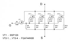
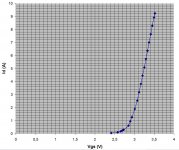
I propose to substitute the IRFP150 by the following composite structure. The BSP129 input capacitance is near 50pF, and transconductance of the composite structure is near 15S, that will give output impedance well below 0,1 Ohms.
Here is a real measured curve at Vds=10V.
I propose to substitute the IRFP150 by the following composite structure. The BSP129 input capacitance is near 50pF, and transconductance of the composite structure is near 15S, that will give output impedance well below 0,1 Ohms.
Here is a real measured curve at Vds=10V.
Attachments
Last edited:
A very pretty commercial follower using battery bias and a different MOSFET with a resistor load.
6moons audio reviews: Nowe Audio mono3.5
6moons audio reviews: Nowe Audio mono3.5
A very pretty commercial follower using battery bias and a different MOSFET with a resistor load.
6moons audio reviews: Nowe Audio mono3.5
Looks like a BJT (Darlington) common collector follower with 3,5A current. Nice toy, but not impressive. Also one may ask whether current consumption from PS is constant under signal. It is a key point for superb sound.
No darlington.
'Description: The manufacturer lists ultra-fast Toshiba TPCA Mosfets; 60-watt high-power MP2060 Kool-Pack and MK-132V Micronox precision resistors by Caddock; WBT Nextgen 0210 and 0710 silver terminals and RCAs; rhodium-plated Furutech IEC; ultra-fast General Semiconductor FES16BT rectifiers; Siltech G6 silver/gold hook-up wiring in Kapton dielectric; Nippon Chemi-Com low impedance LXZ 105c filter capacitors; Wima MKP 10 polypropylene capacitors; Lachowski mains transformer; and Energizer Ultimate 9V battery bias. '
As for impressive, it's mostly money spent on the chasis and termination. A WIMA MKP 10 at the input? No thanks. Not so sure about the output coupling cap either.
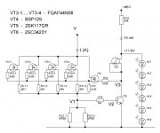
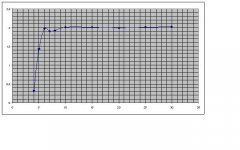
Next step in the Follower 99 implementation is current source approach (the bottom transistor in the original schematics). I have put together and measured the following current source and, at approximately 2A current, tested current stability vs voltage variation.
Current stability is very good, except for a bit strange dip at the low voltage region.
Current stability is very good, except for a bit strange dip at the low voltage region.
Attachments
No darlington.
'Description: The manufacturer lists ultra-fast Toshiba TPCA Mosfets; 60-watt high-power MP2060 Kool-Pack and MK-132V Micronox precision resistors by Caddock; WBT Nextgen 0210 and 0710 silver terminals and RCAs; rhodium-plated Furutech IEC; ultra-fast General Semiconductor FES16BT rectifiers; Siltech G6 silver/gold hook-up wiring in Kapton dielectric; Nippon Chemi-Com low impedance LXZ 105c filter capacitors; Wima MKP 10 polypropylene capacitors; Lachowski mains transformer; and Energizer Ultimate 9V battery bias. '
As for impressive, it's mostly money spent on the chasis and termination. A WIMA MKP 10 at the input? No thanks. Not so sure about the output coupling cap either.
In the 6moon review they say about common collector (not drain) stage, and the big electrolytics is present near the out terminals.
Dunno how much they know about drains but there is a picture of a TPCA8016 in the article. Not sure what you mean about 'the big electrolytics'. The circuit is very clear and extremely easy to reverse.
Dunno how much they know about drains but there is a picture of a TPCA8016 in the article. Not sure what you mean about 'the big electrolytics'. The circuit is very clear and extremely easy to reverse.
Please post this circuit if possible, I suspect the output electrolytic cap is there.
Too lazy to draw. Of course the electrolytic is at output, how else could it be?
Input passes through the .22uF Wima. Battery bias of +9v where negative terminal is grounded through a resistor and positive goes to gate stopper. Drain goes to Vcc and source, through a power resistor goes to ground. Dubious electrolytic couples load.
Input passes through the .22uF Wima. Battery bias of +9v where negative terminal is grounded through a resistor and positive goes to gate stopper. Drain goes to Vcc and source, through a power resistor goes to ground. Dubious electrolytic couples load.
Last edited:
Too lazy to draw. Of course the electrolytic is at output, how else could it be?
Input passes through the .22uF Wima. Battery bias of +9v where negative terminal is grounded through a resistor and positive goes to gate stopper. Drain goes to Vcc and source, through a power resistor goes to ground. Dubious electrolytic couples load.
Is using the battery gate bias really best solution for a sound? I plan to use red diodes for the input transistor gate bias, but maybe it should be changed to 2x9V = 18V battery bias with respect to the positive rail (Follower 99) ?
Is using the battery gate bias really best solution for a sound?
Using a battery in a commercial product is a real pain in the butt. They have definitely listened and liked what they heard in order to go to such an extreme. Battery bias certainly sounds good with tubes, at least in amplifiying stages. In a follower the advantage is less obvious. It's certainly easy enough to try. Out of practical considerations and reliability i would not use batteries but rather go for LEDs or a regulator.
I thought about building a follower, but with a little twist- run two followers off of each side of a differential pair (such as the zen balanced line stage) and do away with the output cap. I had a schematic going one time that was completely direct coupled and used X feedback on the front end. I opted to build an Aleph X instead.
- Status
- Not open for further replies.
- Home
- Amplifiers
- Solid State
- Power Follower 99 sound impressions?