Predator864 said:Aaaaaaand meee ?
There are different variants, which can suit you.
I'll describe it today evening
Nafanja,
I have read post #106 - #108 and I am not quiet sure I understand well what you mean.
My project is that simple: DAC with voltage output (and there is why the caps between the tubes and the output of the DAC), and 1 tube 6H6P-i in cathode follower configuration (let's assume that only 1 tube will be used by now). The transformer that I would love you to make, is to power the tube(s), given that fact that I already have another oversized toroidal powering the DAC.
The designer of the circuit which I sent you by email, recommends 12 V (constant or alternate, at your personal taste) for the filaments, after having test very much the DAC with different configurations and other tube designs.
You recommendation of stabilizing the filaments is welcomed, so I will use 2 caps and a diode rectifier bridge to get 12V constant. Thank you for that, I appreciate it.
As for the transformer, and from my point of view, I can only say that I need 1 primary 230VAC, and 2 secondaries: 110 and 12 VAC. The point in discussion, from my perspective, is how many Amps do we need given the circuit and consumption of the 6H6P. I estimated 1 Amp. for the filament (12VAC secondary), so let's say 2 Amps if we connect 2 tubes instead of one, and roughly less than 1 Amp. for the other secondary @120AVC. The designer of the circuit I sent you specifies this transformer as a power supply: 230 : 120 : 12 VDC 30 VA
http://www.lampizator.eu/LAMPIZATOR/LAMPUCERA/LAMPUCERA DAC/Lampucera_boxed.html
I am not sure I understand well the rest of your post, but I certainly appreciate any recommendation for the trafo ....
I look forward to your comments,
Pepe
Hello Pepe
About 12V.
I make it curtanly.
2 A ...
Dataheet for feelament is 6.3V.
Ukraine was be the USSR.
And there was many tubes like institutes and military factories and military base...
Russia is USSR was too.
But if this Lampizator use RC fllter for filament - I am indestand...
But if you have your oun thinking, please try...)))
I am about cap.
Cap is between DAC and tube and at the output.
May be use accumulator -3V...
At the output - may be think about transsformer?
But I think it's > clearly for you(what is beter-cap or transformer)...
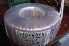
At the nearest time I will show you the amorph trafo...(the picture)
About 12V.
I make it curtanly.
2 A ...
Dataheet for feelament is 6.3V.
Ukraine was be the USSR.
And there was many tubes like institutes and military factories and military base...
Russia is USSR was too.
But if this Lampizator use RC fllter for filament - I am indestand...
But if you have your oun thinking, please try...)))
I am about cap.
Cap is between DAC and tube and at the output.
May be use accumulator -3V...
At the output - may be think about transsformer?
But I think it's > clearly for you(what is beter-cap or transformer)...
At the nearest time I will show you the amorph trafo...(the picture)
Dear Nafanja,
thank you for taking the time to explain that to me, I really appreciate it.
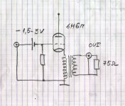
The following pictures are draws about what I understood from the specs of the 6H6P and what you said:
So following your indication, heaters will be 6,3V (either DC retified or AC directly) at @2A . Therefore, I need 1 secondary of the transformer to be 6,3VAC @2A.
The other secondary, again : 120 VAC @1A (Which I will rectify). I decided to use 1 tube only, and try to make things simple and easy.
Having clear that part, then you talk about 2 caps on the design:
The C1 cap on the picture is a decoupling cap (given the DAC is voltage output), as you know of course, but here you recommend... a battery or accumulator of about -3V for autobias or something ?, this is interesting... I would love to hear more !!
The other cap you talk about is the one that is just by the RCA connector. Do you recommend using a trafo there ???, I am not sure I understand...what would you do ? (my electronics are not that good, as you see...). what will be the benefit of a trafo there ?
And finally you mention an "amorph" trafo , I'm afraid I am not familiar with this... which will be the benefit ??
Thank you very much for you patience and understanding, my english is not that good and I find difficult to explain here the details of my project.
I look forward to you comments, and again...thank you !!
Pepe
thank you for taking the time to explain that to me, I really appreciate it.
The following pictures are draws about what I understood from the specs of the 6H6P and what you said:
An externally hosted image should be here but it was not working when we last tested it.
An externally hosted image should be here but it was not working when we last tested it.
So following your indication, heaters will be 6,3V (either DC retified or AC directly) at @2A . Therefore, I need 1 secondary of the transformer to be 6,3VAC @2A.
The other secondary, again : 120 VAC @1A (Which I will rectify). I decided to use 1 tube only, and try to make things simple and easy.
Having clear that part, then you talk about 2 caps on the design:
An externally hosted image should be here but it was not working when we last tested it.
The C1 cap on the picture is a decoupling cap (given the DAC is voltage output), as you know of course, but here you recommend... a battery or accumulator of about -3V for autobias or something ?, this is interesting... I would love to hear more !!
The other cap you talk about is the one that is just by the RCA connector. Do you recommend using a trafo there ???, I am not sure I understand...what would you do ? (my electronics are not that good, as you see...). what will be the benefit of a trafo there ?
And finally you mention an "amorph" trafo , I'm afraid I am not familiar with this... which will be the benefit ??
Thank you very much for you patience and understanding, my english is not that good and I find difficult to explain here the details of my project.
I look forward to you comments, and again...thank you !!
Pepe
For the Pepe
You are best in English...
I think my English is bad....
Tell me please what do the DAC do you plan?
TDA1541, AD1862,PCM...
I will give the picture tomorow...
The macket with trafo.
Don't afraide the amorph trafo. He is a little and kindly...
You are best in English...
I think my English is bad....
Tell me please what do the DAC do you plan?
TDA1541, AD1862,PCM...
I will give the picture tomorow...
The macket with trafo.
Don't afraide the amorph trafo. He is a little and kindly...
Hi Nafanja,
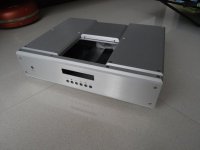
This is the DAC than I am using:
It is a little gem, the size of a credit card. It has this great DAC chip: Cirrus Logic CS4397 paired with a great receiver chip: Cirrus Logic CS8416. This is an ultrafast 24 bit 192Khz format, which also reads redbook CD format 16/44.
If you mod this little baby, like changing the SMD caps for blue OS-CONS, change the bypass caps for Wima or something similar, and also change the Operational amplifier (the socket that appears on your right hand side in the picture), you've got then a DAC that sounds like others of several thousand dollars.
This DAC is of a voltage type, as you see is different from the TDA1541 which outpus current instead of voltage.
I am a "tube" kind of person (my amplifier is a vacum tube one), so I want to mod the digital output stage of this DAC (the operational amp) and substitute for a tube stage ... the picture that I posted before with the schematics. In that way, I'll have the beauty of tube sound ..... that's it.
I will look forward to you pics, mods or anything you'd like to share. I love modding ....
Best,
Pepe
This is the DAC than I am using:
An externally hosted image should be here but it was not working when we last tested it.
It is a little gem, the size of a credit card. It has this great DAC chip: Cirrus Logic CS4397 paired with a great receiver chip: Cirrus Logic CS8416. This is an ultrafast 24 bit 192Khz format, which also reads redbook CD format 16/44.
If you mod this little baby, like changing the SMD caps for blue OS-CONS, change the bypass caps for Wima or something similar, and also change the Operational amplifier (the socket that appears on your right hand side in the picture), you've got then a DAC that sounds like others of several thousand dollars.
This DAC is of a voltage type, as you see is different from the TDA1541 which outpus current instead of voltage.
I am a "tube" kind of person (my amplifier is a vacum tube one), so I want to mod the digital output stage of this DAC (the operational amp) and substitute for a tube stage ... the picture that I posted before with the schematics. In that way, I'll have the beauty of tube sound ..... that's it.
I will look forward to you pics, mods or anything you'd like to share. I love modding ....
Best,
Pepe
Re: power trans and chokes
Hi XianYang,
I recomend core = iron+chrome.
section area: 10 square cm
You can choose 2 types of isolation: paper or teflon.
Weight of choke about 1,5 kg/piece
The chokes all together cost 60$
Tranformers: a good one costs 60$ and has weight about 3kg
hi-end quality one costs 90$ and has weight 5kg
dukekiong said:Hi nafanja,
i have a custom toroidal power trans and a couple of chokes made.
toroidal power trans:
primary - 115x2 50Hz/60Hz
secondaries - 0-240V @ 0.2A + 0-18V @ 1.0A + 0-18V @ 1.0A + 0-18V @ 1.0A + 0-7V @ 2.0A
roughly 116VA
tube amp supply choke
10H @ 100ma (1 required)
20H @ 50ma (2 required)
what cores do you recommend for chokes for best peformance/efficiency?
please give me a quote and it would be great if you can also provide me with the dimensions and weight of the transformers.
Thank you,
XianYang
Hi XianYang,
I recomend core = iron+chrome.
section area: 10 square cm
You can choose 2 types of isolation: paper or teflon.
Weight of choke about 1,5 kg/piece
The chokes all together cost 60$
Tranformers: a good one costs 60$ and has weight about 3kg
hi-end quality one costs 90$ and has weight 5kg
For Pepe
Hellp Pepe...
As I see
http://www.cirrus.com/en/pubs/rdDatasheet/cs43122eb-1.pdf
you may not use cap from DAC to Tube.
I think that it's anti-shoke...But I think - that is the scheme will be made acurasy - all will be OK.
Hellp Pepe...
As I see
http://www.cirrus.com/en/pubs/rdDatasheet/cs43122eb-1.pdf
you may not use cap from DAC to Tube.
I think that it's anti-shoke...But I think - that is the scheme will be made acurasy - all will be OK.
Attachments
For Pepe
Hellp Pepe...
As I see
http://www.cirrus.com/en/pubs/rdDatasheet/cs43122eb-1.pdf
you may not use cap from DAC to Tube.
I think that it's anti-shoke...But I think - that is the scheme will be made acurasy - all will be OK.
The schemes wioth picture is here
Hellp Pepe...
As I see
http://www.cirrus.com/en/pubs/rdDatasheet/cs43122eb-1.pdf
you may not use cap from DAC to Tube.
I think that it's anti-shoke...But I think - that is the scheme will be made acurasy - all will be OK.
The schemes wioth picture is here
Attachments
Hi Nafanja,
thank you very much for the schematics and your comments, I will skip the C1 coupling cap then.
What I dont understand well is the effect of the trafo at the cathode of the tube. This is the schematics that I am implementing:
Could you please explain the benefit of using that trafo at the cathode ?.
I think that the trafo that I need for powering the tube taking into account your comments is the following one:
1 primary 230VAC
2 secondaries: 120VAC @1A , 6,3VAC @2A
What do you think?, how much will be that ?
Best,
Pepe
thank you very much for the schematics and your comments, I will skip the C1 coupling cap then.
What I dont understand well is the effect of the trafo at the cathode of the tube. This is the schematics that I am implementing:
An externally hosted image should be here but it was not working when we last tested it.
Could you please explain the benefit of using that trafo at the cathode ?.
I think that the trafo that I need for powering the tube taking into account your comments is the following one:
1 primary 230VAC
2 secondaries: 120VAC @1A , 6,3VAC @2A
What do you think?, how much will be that ?
Best,
Pepe
Pepe
Hello Pepe.
For the sound need quelity cap.
You have pulsation of curent and you will need good capacitance.
I know man. who build ultra-high-end. He use in his RIAA near 400 MF (no electrolitic). or more.
But have oinion that trafo is better than cap.
But it's opinion.
If teoreticaly-
Zout = 65.5 Ohm.
With resistor Rcathode = 330 Ohm.
LR - R = 47 OHm.
With transformer Rout= Zout 65.7 Ohm=Rcathode
47000-470/65.7 = n
(The last resistor)
Slew rate is more near = n more
(We work on the input capacitance of next tube or transistor)
The transformer with near >100 Henru is the
near o Hz (-odb). The high frequency will me near 500 kHz and >...maby 1.5 Mhz...
Low faze distortion too.
High Slew rate is that you will hear...
You will make the dofference after the hearing.
If you will likwe - it. I will back the money (trafo too)))
The price for the toroid will be the same...
Hi Nafanja,
thank very much for the schematics with your designs, it sounds very interesting. I still don't get quite well the benefit of your design instead of a capacitor (I have bought some Obliggato paper in oil for this job), as I said my electronics are not that good as to understand the whole thing, but I trust your recommendation. If the price is not high, I guess will try it ....
So if I understand well, I need 2 trafos right ???, 1 to power the 6H6P and 1 more replacent the capacitors that I had in my original design, and that you pictured in your post.
Could you please send me (by private email if you prefer) the final quote for the 2 transformers (the toroid that I need and the one you suggest) ?
Thank you and best regards,
Pepe
lindamar said:Hi Nafanja,
thank very much for the schematics with your designs, it sounds very interesting. I still don't get quite well the benefit of your design instead of a capacitor (I have bought some Obliggato paper in oil for this job), as I said my electronics are not that good as to understand the whole thing, but I trust your recommendation. If the price is not high, I guess will try it ....
So if I understand well, I need 2 trafos right ???, 1 to power the 6H6P and 1 more replacent the capacitors that I had in my original design, and that you pictured in your post.
Could you please send me (by private email if you prefer) the final quote for the 2 transformers (the toroid that I need and the one you suggest) ?
Thank you and best regards,
Pepe
Hi Pere,
which core would you like ?
Amorph Cobalt or amorrph steel?
Hi Nafanja,
I thank you for answering my post. What if you quote both cobalt and steel ??
To be honest with you, I don't know the difference between the 2 ...
Best,
Pepe
I thank you for answering my post. What if you quote both cobalt and steel ??
To be honest with you, I don't know the difference between the 2 ...
Best,
Pepe
- Status
- Not open for further replies.
- Home
- Vendor's Bazaar
- Power and Output transformers for sale