I note from an image in post 3 that the input RCA connectors are very close to the some output cables. The a.c. currents in these outputs due to magnetic radiation have potential to induce currents in the input wires. These may be shielded to prevent this but the shield needs to be earthed at one end
Normal practice is to specify separate equal secondary windings and from colour coding on the insulation tube leads to work out which winding mates with the correct partner so a centre tap can be formed with correct phase for the secondaries. The code information should be on a the sticker on the side of the toroid.
I hope our member is are not using the switch mode supply arrangement for his replacement transformer power supply.Boom, there you have it. In recording studios or listening rooms, that is a culprit. If you haven't already-
In sequence you require:
1. A good earth, if you can get less than 0.5Ω awesome (very specialised meters required), driving copper rods ( 3 interconnected rods are the IEEE standard for a mains supply) will not always get you there, depending on the conductivity of your available earth, dryness, for example is rarely good, As short as possible over engineered cable helps weather the elements as well as keeps the Resistance down.
2. A dedicated mains spur from the fuse/ breaker box.
3. Then to star earthing inter equipment to prevent loops that pick up interference, like RF , 50Hz buzz, etc.etc.
4. Yes, sequencing power up is a 'thing' in all larger systems. if you can't alter this spur arrangement, and long runs of cables are involved, there is the compromise of Input and Output transformers on the interconnect, like Mixing Console to Stage and D.I. boxes.
Like all Electrics and Electronics each one of these has the potential to be a rabbit hole of research. Zoom out after each session!
If your explorations are to be assisted, defining what, where and types is helpful. May I hesitantly suggest reading back to yourself what you write, asking your self does this mean what I'm trying to say? Does it allow others to 'get your drift'? I use the preview function, it helps.
Where? Input or output of the LMxx? it's easy enough to download the PDF and start with the manufacturers recommendations. In my experience, increasing low ESR caps values on the outputs decreases general noise.
Going beyond the manufacturers recommendations on the input doesn't make much difference, but using a cap there will help keep the output as clean as possible.
Pointless.
Think of all the time and money you could be saving by putting in a 4mm² or 6mm² 'Twin and earth' supply. Not to mention headaches. Not recommended unless you have real experience in mains electricity, but not expensive.
Not A 4mm ø cable.
2.3mm ø copper is 4mm²
6mm² is 2.8mm ø
Cross Sectional Area
This is a good circuit type for mains filtration for SMPSs:
Note the capacitors from both lines to earth AFTER the double choke/ compensating inductor, very important, then the inductor to E
Supply is left. Load is right.
View attachment 1444698
The 'back to back' zener diode arrangement may be an interesting isolated experiment... Using the above diagram, where the single capacitor to earth is, after the transformer/ inductor, as it were, except it would be to chassis in your earlier context.
It's a very long time since I've used that and i'm struggling to find a reference in my files,
but I think it serves as a dissipative function in some earthing situations.
It's best to eliminate fundamental problems first, like your spur loops. At least then you know what is what.
hope that helps.
Normal practice is to specify separate equal secondary windings and from colour coding on the insulation tube leads to work out which winding mates with the correct partner so a centre tap can be formed with correct phase for the secondaries. The code information should be on a the sticker on the side of the toroid.
I'm bad for acronyms, but what is "CU"
Consumer Unit I used one on before, this was 2008, I moved from here in 2013. I did A-B as I had the existing ring main in place
each line was fused individually
Mjona, hiI note from an image in post 3 that the input RCA connectors are very close to the some output cables. The a.c. currents in these outputs due to magnetic radiation have potential to induce currents in the input wires. These may be shielded to prevent this but the shield needs to be earthed at one end
I hope our member is are not using the switch mode supply arrangement for his replacement transformer power supply.
Normal practice is to specify separate equal secondary windings and from colour coding on the insulation tube leads to work out which winding mates with the correct partner so a centre tap can be formed with correct phase for the secondaries. The code information should be on a the sticker on the side of the toroid.
No swicthmode for any supplies in the whole set up, apart form a PC that is off when any DSP adjustments have been made and the projector that is off when any measurements taken and is connected to the video processor via a fire cable and powered by an individual spur.
When the transformer is powered remotely the and connected with loose leads to allow some trial dressing no noticeable difference unfortunately
Just to riterate the noise I want to reduce now is predominately 'hiss' or equivalent, very little mains low frequency noise now
The Ground Loops presentation (near the back) talks about making sure all pieces of gear come off the same mains outlet if the gear utilises a safety ground. If you are powering gear in a system off separate ring mains you have a huge loop area for mag field pickup and therefore noise.
Andrew, thanks
In a perfect world I would have used one CU (consumer unit) with a direct or very low impedance supply to the CU then matched low impedance spurs each fused at the CU. Ive done this before a number of times and it was great. Alas where I live now I am unable to do that. The set up I have is a direct fed CU on the second floor with a separate ring for the AV set up, all plugs on the back wall. My only earth to signal GND is at the BR player and all GND connections from units have been improved to reduce any voltage differnces the existing sub unit was quiet (BPSP 500) the BK1K is plugged into the same connections in the same location as I want to replace the 500's feeding my 18" subs.
First of all I see there are many imbalances in the overall headroom considerations
For 12 Mosfets you have just 4 x 10000uF cap and that too for subwoofer application is very low capacitance you need hefty capacitance as ripple current demand will be quite high. Afaik you need atleast 60,000uF/Rail and those puny capacitors will not be able to handle the ripple and they would get puntured in bad load conditions as most of the subs run in 4ohm load.
Bridge rectifier is open air cooled they need to be heatsinked as they get quite hot once you are playing at high power subwoofers.
Get the speaker return which is - of the speaker to point to the junction of the capacitor in between +/- terminal of the mains power capacitor
Yes interesting idea, Ive always fancied trying these items https://www.hificollective.co.uk/catalog/mlhc100030-47000uf-100v-mlytic-electrolytic-p-3981.html. ! But I wood be going down another rabbit hole !
The subs are these
https://bmsspeakers.com/index.php-11.html?id=bms_18n862 in 4Ohm not 8 Ohm
That's a bit of a change from the graphs you've posted?....
Just to riterate the noise I want to reduce now is predominately 'hiss' or equivalent, very little mains low frequency noise now
That's a bit of a change from the graphs you've posted?
Yes I am ignoring the blue area as this is clearly misleading the green seems to correlate too what I hear. The black is the totally silent BPSP 500 the brown the evolved BKL1000, this is still audible at the seating position.
I did try to complete a loop back test but this wasn't possible, the speaker is useful to 1K then falls away anyway, hence looking at the green are
This is the SPL at the seating position with one of the 18" subs on a test sweep keeping distortion below 5%

The green area is dominated by harmonics of 50Hz.Yes I am ignoring the blue area as this is clearly misleading the green seems to correlate too what I hear. The black is the totally silent BPSP 500 the brown the evolved BKL1000, this is still audible at the seating position.
I did try to complete a loop back test but this wasn't possible, the speaker is useful to 1K then falls away anyway, hence looking at the green are
View attachment 1445196
...
You can't see the gaps between the harmonic spikes due to the width of the filter.
If that was an RF spectrum analyser plot, I would be reaching to reduce the resolution bandwidth.
There's a lump at ~25Hz. Then there's intermod-esque sidebands on all the harmonics at ~25Hz delta.
The frequency of that 20-something Hz lump changes between the black and brown traces.
It might be prudent to understand that. If you repeat the scan, does it move?
Consumer unit/ Switch Board/ Fuse Box/ Breaker board.
Ta.
Hiss. Hmmm. Where? All equipment has background noise characteristics.
Still, with an extensive system, the crap that now comes through our mains electric plays a larger role than it used to,
even a decade ago it wasn't that bad.
I find the 3am test the easiest one.
If it sounds as good in the wee small hours as it does through the day, you have well designed power supplies.
if not, yeah maybe it's time to look at filtration of the incoming mains.
I recently spent three years on and off looking into this nightmare, building on three decades of observations from experience.
Generally, there are around twelve or thirteen types of mains interference/ problems.
Every locale will have its characteristics, as does the equipment connected.
This is too large a topic at this time for me to 'flesh out' a coherent overview. and frankly not something I feel comfortable sharing over a public forum.
Here's the X-men of power filters: Furman P-2300 IT E

The noise floor cancellation design is as far as i am aware, second to none on the market presently, probably best deployed on all source and pre.
That will get rid of the worst, depending on what your particular contextual 'worst' is!
It will give you that 'black background' though.

or Sinalda systems, pretty good general protection and filtration, better for larger current draw audio such as amps.
Localised (within house) low pass filtration of SMPS is the way to go. Kill it at source.
But of course, the triplins harmonics thru the mains is on the increase.
Try finding 100A Low pass filters, basically.
Ta.
Hiss. Hmmm. Where? All equipment has background noise characteristics.
Still, with an extensive system, the crap that now comes through our mains electric plays a larger role than it used to,
even a decade ago it wasn't that bad.
I find the 3am test the easiest one.
If it sounds as good in the wee small hours as it does through the day, you have well designed power supplies.
if not, yeah maybe it's time to look at filtration of the incoming mains.
I recently spent three years on and off looking into this nightmare, building on three decades of observations from experience.
Generally, there are around twelve or thirteen types of mains interference/ problems.
Every locale will have its characteristics, as does the equipment connected.
This is too large a topic at this time for me to 'flesh out' a coherent overview. and frankly not something I feel comfortable sharing over a public forum.
Here's the X-men of power filters: Furman P-2300 IT E
The noise floor cancellation design is as far as i am aware, second to none on the market presently, probably best deployed on all source and pre.
That will get rid of the worst, depending on what your particular contextual 'worst' is!
It will give you that 'black background' though.
or Sinalda systems, pretty good general protection and filtration, better for larger current draw audio such as amps.
Localised (within house) low pass filtration of SMPS is the way to go. Kill it at source.
But of course, the triplins harmonics thru the mains is on the increase.
Try finding 100A Low pass filters, basically.
Last edited:

Earth, hi
I have experimented a lot with mains filtration over the the years, but alas I've always found there is a trade with dynamics and lowering the noise floor when in series. I borrowed a huge Isotek when first they hit the market and have tried a number since. I have never got on with series filters that add impedance but I have got on with parallel filters focussing on differential noise.
I have a few of these near preampfification and source unit supplies. I ended up making them
I'm going to modify the GND on the other board to 'match' the better board with the mods and see if I can measure the power rails with my new Scope
Earths,hi
"Where? Input or output of the LMxx? it's easy enough to download the PDF and start with the manufacturers recommendations. In my experience, increasing low ESR caps values on the outputs decreases general noise.
Going beyond the manufacturers recommendations on the input doesn't make much difference, but using a cap there will help keep the output as clean as possible."
The 0.47uF was close to the recommended 0.33uF so I added this, are you suggesting something like a low ESR (Panasonic FR) 100uf cap added as well, I could add more or less ?

+
"Where? Input or output of the LMxx? it's easy enough to download the PDF and start with the manufacturers recommendations. In my experience, increasing low ESR caps values on the outputs decreases general noise.
Going beyond the manufacturers recommendations on the input doesn't make much difference, but using a cap there will help keep the output as clean as possible."
The 0.47uF was close to the recommended 0.33uF so I added this, are you suggesting something like a low ESR (Panasonic FR) 100uf cap added as well, I could add more or less ?
+
Attachments
Wow, I see your prototyping for the Mars Rover!
Tell me they're not polypropylene!
NiZn ferrites cores with the 240AC wires tight wrapped 3 1/2 times around the core

and a couple of 10nF X rated to E

Tell me they're not polypropylene!
Yes, differential mode interference was the one that I found caused most problems, particularly for the reliability of digital devices.focussing on differential noise
NiZn ferrites cores with the 240AC wires tight wrapped 3 1/2 times around the core
and a couple of 10nF X rated to E
Last edited:
Yes. Maybe go polymer on the 100µF.The 0.47uF was close to the recommended 0.33uF so I added this, are you suggesting something like a low ESR (Panasonic FR) 100uf cap added as well, I could add more or less ?
Have you asked your self what function that Zener performs? they are noisy.
7815 noisy too, plenty low noise regs out there.
I have a couple of small toroidal Transformers so will feed via W04M rectifier and 2,200uF cap circa 20V to replace the 24V supply to the L7812CV
I already have a small 12V equivalent for the 12V fan that works fine on a temperature switch I assume this will be the best way to wire the transformer ?
It's a 0-115-0-115 and a 2 x15V transformer

I already have a small 12V equivalent for the 12V fan that works fine on a temperature switch I assume this will be the best way to wire the transformer ?
It's a 0-115-0-115 and a 2 x15V transformer
Earths,hi
"Where? Input or output of the LMxx? it's easy enough to download the PDF and start with the manufacturers recommendations. In my experience, increasing low ESR caps values on the outputs decreases general noise.
Going beyond the manufacturers recommendations on the input doesn't make much difference, but using a cap there will help keep the output as clean as possible."
The 0.47uF was close to the recommended 0.33uF so I added this, are you suggesting something like a low ESR (Panasonic FR) 100uf cap added as well, I could add more or less ?
View attachment 1445652
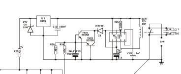
One might look at the 7815 data sheet for IC as the output impedance of this device this will reduce if C12 is replaced by a tantalum capacitor of 1uF. I would ask if you really need a voltage zener for this part of your circuit - if you need 12 volts that is within the nfb capability of the 7815 which has current limiting as well. The zener diode could be replaced by a simple resistor divide to feed the 7815 - probably 24 volts.
I will check how it operates today, time allowing, I have added a 15VA toroid with a rectifier and 2,200uF cap. I have fed this in to the board at the location of the 24V supply to the anti thump circuit. I can measure voltages. I think I will be near 20V under load to the 7812. I hope any noise will not be hitting the circuit now as no long to the main board I removed the GND link
The 12V fan is on a temperature control so the small 3VA supply is only powered when required. (PS I will ensure everything is electrically insulated when finished)
I could do some measurements to use a resistor instead of the diode to the 7812, but my little supply is unregulated


The 12V fan is on a temperature control so the small 3VA supply is only powered when required. (PS I will ensure everything is electrically insulated when finished)
I could do some measurements to use a resistor instead of the diode to the 7812, but my little supply is unregulated
Well all works as expected, well nearly - it's made the whole problem worse from a feedback and noise perspective. I wired in the feed to the anti thump circuit undependently so the circuit was only fed from the power supply and not linked to the amp circuit. Much noisier, so I experimented and it was better with a connection to signal GND
Overall looks like a 'noisy' 7w voltage dropper is currently better
Black the 'target' the existing 500W amplifier. Silent in operation, (I am unsure about the 50Hz peak as not audible)
light green BK1000W amp direct from DSP with the 'new' power supply to the 12V anti thump circuit
Blue BK1000W and direct feed from DSP with new power supply but also a link from the new anti thump circuit supply GND and signal GND
Dark Green BK1000W with existing voltage drop to supply the anti thump
All the measurements with REW measuring no signal from power amp output
- Home
- Amplifiers
- Solid State
- Power amplifier noise from chassis EARTH - any ideas?