Hi Shawn
You're starting to become dangerous. Nice work.
Only one concern, what rating is your bridge. It looks a bit light on.
Cheers
Quasi (Quatro, Q, etc....)
You're starting to become dangerous. Nice work.
Only one concern, what rating is your bridge. It looks a bit light on.
Cheers
Quasi (Quatro, Q, etc....)
quasi said:Only one concern, what rating is your bridge. It looks a bit light on.
Q,
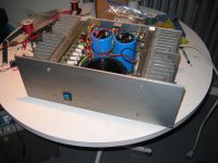
It is rated @10 amps! It will supply 40-0-40 DC into one channel with 6 Fet's. I think it is more than enough for such a small amp 😉
Shawn.
It has an eye to bolt on a heat sink???


Hi guys,
Thanks for your helps,
I remember I measured bias current when the amp is warm enough(15 minutes), but tonight I will test it again, hope it'll be OK.
At first, I only intended to build 1 module for my bassamp, but as you said, maybe I will build another one, as soon as I have time, and money of course( Quasi, you know your amp costs much, hah?), and then I can compare the 2 amp.
About the voltage across R12, R15 and R22, you can see that those resistors are under the driver heatsink, so it's hard to measure, but I'll try.
Again, thanks you guys very much,
Regards,
Duong.
Thanks for your helps,
when setting up the amplifier, you should
1. remove all loads from the output.
2. insert a shorting plug into the input RCA.
3. adjust the DC output offset.
4. adjust the output stage quiescent current.
repeat 3 & 4 until conditions stabilise. This will take longer than 10minutes for the heatsink to warm up.
Switch off and allow all to go cold, do not make any adjustments.
Power up and recheck the DC offset and output bias from cold and monitor what it does as the amp warms up.
Did the DC offset and bias current behave as the amp went from cold to warm?
Now connect your normal source and check DC offset again.
Any change here indicates DC coming from your source. Fix the source if error is significant.
Now it's safe to connect your speakers and try some music.
I remember I measured bias current when the amp is warm enough(15 minutes), but tonight I will test it again, hope it'll be OK.
Yes, I had my amp run nonstop for 2days with so so level of Metallica( I hope my neiboughs won't call the cops), now it still run well and cool( with DC fan), so perhaps it's Ok now.Hi Duong
If your amp module works (amplifies signal cleanly) then I would go ahead and build the next module. This way you can compare differences between the two and track down the problem of the varying DC offset. You could try changing VR1 and VR2.
VR1 is used to compensate for component tolerances elswhere so the voltage across it may not be 0mV but something else.
The other voltages you have measured tell me that your amp is working fine. Can you please measure the voltage across R22.
Also post the voltages for R12 and R15.
At first, I only intended to build 1 module for my bassamp, but as you said, maybe I will build another one, as soon as I have time, and money of course( Quasi, you know your amp costs much, hah?), and then I can compare the 2 amp.
About the voltage across R12, R15 and R22, you can see that those resistors are under the driver heatsink, so it's hard to measure, but I'll try.
Yes, I always check Hfe of the different pair with my multimeter before solder. In my Quasi amp, I don't remember the exact value, but the two C2240s have the same Hfe, and also are the two MPSA92.DC on the output of any PA should be as low as possible. Its value largely depends on how well the input differential pair is matched. Matching Hfe at say under 100uV base current as in most multimiters is not enough. One should match well Ic currents under given circuit operational base current. Although it may seem complicated there is a very simple way around it.
Treat B-E junction as a diode - collector not connected - and put resistor R in a tested transistor base. Then connect a DC source (eg.battery) of about 10-15V between base resistor and emitter. Choose R value from a well know formula: R=U/i where i=base current as in the actual differential pair (in PA). Measurement accuracy of the voltage drop across the junction should not be worse than 1mV - say 100uV resolution is nice.
So repeat test with as many transistors you have, then choose those, which have close enough junction voltage drop. Then meaure their Hfe (ideally at the same base current) and choose those, which have the closest Hfe.
Hi Shawn, a little question: don't you think +/-40VDC for a Quasi amp is a bit too low, and 60mF ( actually I don't think 60mF, Shawn, with 30mF per rail, it's only 15mF per module, because your caps are in series) is a bit too high for that module?, I wish my amp chassis had more space, so I can put more caps like yours.I purchased the software Quasi used to layout the Quatro PCB's. I always liked his hour glass figures I'll get it in a week or so. I renewed Q's PCB layout for his power supply to handle 60,000uF per Audio Channel of amp. I switched the PCB to accept single "inline" bridge rectifiers with standard leads. I will supply it with 30-0-30 VAC x 1.414 = Approx +/_ 40VDC off of 400 VA toroids hand wound or perhaps from Plitron. Depends how long I take to get ready for them. Six FETs per channel.
Again, thanks you guys very much,
Regards,
Duong.
One more question: I saw in some PSUs they have small caps( usually 0.1uF) in parallel with each diode in the bridge. I don't see those caps in Shawn's PSU, I don't know if those caps are necessary, and what is those caps's job?
Hi Hoan,
the bridge diodes send glitches etc. down strean as they switch on/off.
The diodes can be snubbered to damp out/absorb these glitches by attaching and RC snubber in parallel to each diode.
the bridge diodes send glitches etc. down strean as they switch on/off.
The diodes can be snubbered to damp out/absorb these glitches by attaching and RC snubber in parallel to each diode.
Hi Duong
It looks like Shawn does have 30,000 uF per rail. The capacitors do not appear to be in series.
Some people use a capacitor across the diodes in a rectifier to reduce switching artifacts. I never do and have not experienced any problems with the bridges that I use (slow). Some people use very fast diodes and in some circumstances the capacitors can make a difference.
Cheers
Q
Quasi
Hi Quasi,
Yes, Shawn does have 30mF per rail, but if you consider the 3caps of each rail is one 30mF cap, you can see that 30mF cap of pos rail is in series with the one in the neg rail, so the total cap between pos rail and neg rail is 15mF, that's what I meant. Plz show me if I'm wrong.
One little suggestion: it looks like I use the same software like you to make PCB (Sprint layout), so can you plz send me your original design file of your PSU board? I just want to copy your diode bridge's footprint. Thanks.
Regards,
Duong
Hi Quasi,
quasi said:Hi Duong
It looks like Shawn does have 30,000 uF per rail. The capacitors do not appear to be in series.
Some people use a capacitor across the diodes in a rectifier to reduce switching artifacts. I never do and have not experienced any problems with the bridges that I use (slow). Some people use very fast diodes and in some circumstances the capacitors can make a difference.
Cheers
Q
Yes, Shawn does have 30mF per rail, but if you consider the 3caps of each rail is one 30mF cap, you can see that 30mF cap of pos rail is in series with the one in the neg rail, so the total cap between pos rail and neg rail is 15mF, that's what I meant. Plz show me if I'm wrong.
One little suggestion: it looks like I use the same software like you to make PCB (Sprint layout), so can you plz send me your original design file of your PSU board? I just want to copy your diode bridge's footprint. Thanks.
Regards,
Duong
This is a bit off topic, but would it be possible to release a board designed for P2P output wiring? I'm planning to use a rather large heatsink with shallow fins and I suspect using the current design would yield poor thermal performance.
Also, I'm curious if this amp has been tested into a purely capacitive load? Leach did this on his super amp and ended up redesigning part of it it due to instabilities.
Also, I'm curious if this amp has been tested into a purely capacitive load? Leach did this on his super amp and ended up redesigning part of it it due to instabilities.
Sorry to ask here Quasi
H PM650,
Is there a link to the topic you are talking about the Super Leach? I am sort of half way thru it.
Sorry Quasi, but yours is on my next-to-do list. In fact I am getting the components now (all transistors ready) but the pcb..... It would take me a wild to do it. I would lay my own, just to get better control of everything. But of course a lot of reference from yours and the others.
Oh just one thing more :
When getting power for the front end, we never get it after the fuse (as the output end does). Is this a must? Or can we supply power to both ends after the fuse? Hope I had made my question clear.
When getting power for the front end, we never get it after the fuse (as the output end does). Is this a must? Or can we supply power to both ends after the fuse? Hope I had made my question clear.
There is no topic (that I know of) discussing Leach's tests driving a capacitive load, the info I spoke of is discussed by Leach himself on the Low TIM amp background page.
Those pesky capacitors
Hi Duong,
Sorry I can't agree (that's ok though). The capacitors go from rail to ground so they are not in series. In series capacitors the current flows* through one capacitor and then through the other(s). This does not happen with this power supply. The current flows* through one capacitor only directly to ground.
*by current flows I mean the charging and discharging currents.
I'll send you that PCB layout.
Cheers
Q
bigpanda said:Oh just one thing more :
When getting power for the front end, we never get it after the fuse (as the output end does). Is this a must? Or can we supply power to both ends after the fuse? Hope I had made my question clear.
I always design my amps with fuses only for the output stage. I connect the front end directly to the rails.
Cheers
Q
Part 2
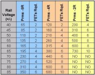
but I want to explore more of the spectrum that Q put up in his selection table. So I am heading to the other side of the road just to see. I don't have much concern about the small-ish rails at +/-40 VDC. I think it will operate fantastically but I will post the results as I am building it anyway.
I exaggerated the power supply to accommodate Mr. T's and Q's tough Soar performance criteria. I am trying to build an amp with no limitations but itself. Each channel will have it's own 400VA transformer and 60,000uF of cap. power supply. I will be using only the best components I can get my hands on. It will be a solid amp. This is my goal and remember the 10 mosfet version I have is solid. I'm just curious I guess. Furthermore, no one that I know of, has built this amp in either direction I went. I want to explore Q's amp in different ways , I guess. Perhaps I just want to be different😀 but I seem to have no problem with that in every day life. 😉 Your comments...
Shawn.
Attachments
AndrewT said:Hi Tomw,
it might make a good candidate for a bridgable amp.
Wow! That never entered my mind. It sure sounds good T. So much Quasi and so little time. 😀
- Home
- Amplifiers
- Solid State
- Power amp under development