hoangduongo said:I found that your DC detector is quite identical to the one from Silicon Chip, except some small change, I think it's because SC use 12V relay, I'll post that schematic later.
Yes the DC detect circuit I posted has been used by at least 3 major electronics magazines in Australia for more than 25 years. It's simple and effective. See http://www.diyaudio.com/forums/showthread.php?postid=776114#post776114
I have changed some of the component values to suit my timing and operating voltage requirements.
Cheers
Q
Hi Quasi,
can you correct the note from R1 to R2. Most will recognise the error but a few may be confused.
can you correct the note from R1 to R2. Most will recognise the error but a few may be confused.
AndrewT said:Hi Quasi,
can you correct the note from R1 to R2. Most will recognise the error but a few may be confused.
Thanks Andrew,
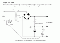
Yes folks post 920 is incorrect. Please refer to this schematic.
Cheers
Q
Attachments
Hi Quasi,
A time honoured circuit indeed. R1 is at least 1/2 that value in 120 VAC land. Your time constant should be on the order of 1/2 sec to 2 sec, before the relay timer connects.
If the amp suffers a failure, R1 is designed to burn out. This is very common in many larger amplifiers. Marantz, Denon and Nakamichi all come to mind (with R1 values ranging from 2R2 to 15 R).
-Chris
Quasi, good work man, i just want to say I admire your work and design ,keep it up, I been abuilding amplifiers since I was in highschool (iam not an expert though) and Im planning to build this design of yours, could you please tell me how to adjust VR1 and VR2, the specs reading and the testpoints,, I really appreciate if you could tell me. Thanks again man.. Nice works 😉
jhoel47 said:... could you please tell me how to adjust VR1 and VR2, the specs reading and the testpoints,, I really appreciate if you could tell me. Thanks again man.. Nice works 😉
jhoel,
I believe you will the document quasi created will be helpful. Please see Post #705:
http://www.diyaudio.com/forums/showthread.php?postid=955022#post955022
To rest on thread,
Sorry all but I am swamped with a number of family, personal and cat matters the past 3 weeks or more. I therefore have not been about to help out here and respond to some of the outstanding postings. Suitations may still take a few weeks to clear.
Regards,
John L. Males
Willowdale, Ontario
Canada
16 August 2006 03:10
Your very welcome jhoel47, thanks for the interest. Don't forget to post pictures of your work.
Thanks for providing the link John. I hope everything is ok at home.
Cheers
Q
Thanks for providing the link John. I hope everything is ok at home.
Cheers
Q
Thanks again QUASI and keypunch, ill will start with PCB etching, i will use a photo transfer PCB for this project ,much easy than using old ways of etch resist, ill post the PCB picture here when its finish, hope i can do it with less hassle.😀
anatech said:Hi Quasi,
A time honoured circuit indeed. R1 is at least 1/2 that value in 120 VAC land. Your time constant should be on the order of 1/2 sec to 2 sec, before the relay timer connects.
If the amp suffers a failure, R1 is designed to burn out. This is very common in many larger amplifiers. Marantz, Denon and Nakamichi all come to mind (with R1 values ranging from 2R2 to 15 R).
-Chris
I guess the value of the resistor in question depends on a few other things too, ie; transformer size and the amount (number?) of capacitors.
Cheers
Hi Quasi,
-Chris 😉
Yup. And the whim of the designer.I guess the value of the resistor in question depends on a few other things too, ie; transformer size and the amount (number?) of capacitors.
-Chris 😉
anatech said:Hi Quasi,
Yup. And the whim of the designer.
-Chris 😉
Ha so true .....
Quasi, please can you post me the last schematic for this amp? i will build it but i will use the power board of the other amp(remember no negative wave...........)
thanks...
thanks...
Flavio88 said:Quasi, please can you post me the last schematic for this amp? i will build it but i will use the power board of the other amp(remember no negative wave...........)
thanks...
You need to send me an email first. I will then send you The latest schematics, board layout, setup guide and other good stuff.
Cheers
Q
Hi Quasi,
Can you send me all about the latest version of your project ?
My e-mail is antonixx-at-hotmail.com
Can you send me all about the latest version of your project ?
My e-mail is antonixx-at-hotmail.com
Quasi, could you please send me those latest updates of this amp, for some reason I cant send you and email , i dont know why, dont have rigths perhaps, anyway here is my mail add : joel_m@pimes.com.ph, tnx again bro..🙂
Hi Q,
Can I have a copy of the detail documents also? I am starting on your project now.
Tks a lot
tony_chan_cf@yahoo.com.hk
Can I have a copy of the detail documents also? I am starting on your project now.
Tks a lot
tony_chan_cf@yahoo.com.hk
- Home
- Amplifiers
- Solid State
- Power amp under development


