Hi Matt,
why do you consider high power is required to drive top and mid speakers?
The Quasi is a good, cheap way to get high power into a less efficient wideband speaker assembly or particularly to drive a low sensitivity/very low frequency bass driver.
why do you consider high power is required to drive top and mid speakers?
The Quasi is a good, cheap way to get high power into a less efficient wideband speaker assembly or particularly to drive a low sensitivity/very low frequency bass driver.
Hi Andrew, the mid/tops are 4 x 12" 300watt cabs, so they require a fair amount of power. I am currently running some Holton lateral amps I made up with my own board layout, but I'm having a rejig and I'm looking at some other options!
Request for info
Please send me the The latest schematics, board layout,
setup guide and other good stuff.
I emailed you but never recieved an email.
ppcblaster@zoominternet.net
Thank You.......Gary
quasi said:
You need to send me an email first. I will then send you The latest schematics, board layout, setup guide and other good stuff.
Cheers
Q
Please send me the The latest schematics, board layout,
setup guide and other good stuff.
I emailed you but never recieved an email.
ppcblaster@zoominternet.net
Thank You.......Gary
inductor
Hello, I was wandering, Quasi how would I wind the 4 uH Inductor. What size wire should I use and how many turns on which diameter should I wind?
Hello, I was wandering, Quasi how would I wind the 4 uH Inductor. What size wire should I use and how many turns on which diameter should I wind?
Hi Big,
you need to monitor the current by metering across the resistor.
If the Vgs varies even slightly the voltage across the resistor also varies. That rubbishes the results.
You should have a way to slightly adjust the supply voltage to enable a constant current through the monitoring resistor and then read off the Vgs.
The constant current can be adjusted by adding a second adjustable resistor above the one you have shown or by using a variable PSU set to constant current mode or adjust the output voltage by hand.
You also need to carry out the measurement at constant temperature. You may be able to achieve this by using TIME to get consistent and repeatable results. i.e at exactly 10seconds after applying the power and making your fine adjustments in the intervening period, read your Vgs.
Tks T,
The thing that I don't understand is : if the method is wrong, it should not work for any of them. But what I am having is that some of the voltages is stable but not all. What could be wrong? Can you interpret this further?
Tks
The thing that I don't understand is : if the method is wrong, it should not work for any of them. But what I am having is that some of the voltages is stable but not all. What could be wrong? Can you interpret this further?
Tks
Re: inductor
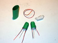
I just wind about 30 turns of 1mm enamelled wire around an air core about 1cm in diameter and 1 cm high. You will end up with about 3 layers. Try to find a plastic bobbin like the one in my pics to make it easier. But don't stress if you can't, have a look at what Shawn did. It looks like he wound some around a 5 watt resistor.
Cheers
davorinjo said:Hello, I was wandering, Quasi how would I wind the 4 uH Inductor. What size wire should I use and how many turns on which diameter should I wind?
I just wind about 30 turns of 1mm enamelled wire around an air core about 1cm in diameter and 1 cm high. You will end up with about 3 layers. Try to find a plastic bobbin like the one in my pics to make it easier. But don't stress if you can't, have a look at what Shawn did. It looks like he wound some around a 5 watt resistor.
Cheers
Hi Quasi, can you send me the details of this amp aswel?
I'm looking to build some new amps for the top/mids in my party setup.
Email: matthew.horner at blueyonder.co.uk
Thanks in advance.
Matt
I'm looking to build some new amps for the top/mids in my party setup.
Email: matthew.horner at blueyonder.co.uk
Thanks in advance.
Matt
matth said:Hi Quasi, can you send me the details of this amp aswel?
I'm looking to build some new amps for the top/mids in my party setup.
Email: matthew.horner at blueyonder.co.uk
Thanks in advance.
Matt
Hi Matt, you have mail.
Cheers
Q
Thanks Quasi, I'm going to have a go at routing the boards out with a CNC router I built a while back.
I'll let you know how it goes.
I'll let you know how it goes.
Inductor
I wound 20 turns 20AWG around 1cm core (physical size of the resistor) and covered with 2.5cm heatshrink tube. Next time around I will use a higher gauge wire and a few more turns.
🙂
davorinjo said:Hello, I was wandering, Quasi how would I wind the 4 uH Inductor. What size wire should I use and how many turns on which diameter should I wind?
quasi said:...have a look at what Shawn did. It looks like he wound some around a 5 watt resistor.
I wound 20 turns 20AWG around 1cm core (physical size of the resistor) and covered with 2.5cm heatshrink tube. Next time around I will use a higher gauge wire and a few more turns.
🙂
Attachments
bigpanda said:Tks T,
The thing that I don't understand is : if the method is wrong, it should not work for any of them. But what I am having is that some of the voltages is stable but not all. What could be wrong? Can you interpret this further?
Tks
Try this to test and match FETs*. You should be able to able to match FETs to the same Vgs. If the FET is faulty you will not be able to adjust the current.
Cheers
Q
Attachments

Re: Re: inductor
Great! How about 1,5 mm*2 isolated wire we use for electric installations. Would that do with maybe a few extra turns?
quasi said:
I just wind about 30 turns of 1mm enamelled wire around an air core about 1cm in diameter and 1 cm high. You will end up with about 3 layers. Try to find a plastic bobbin like the one in my pics to make it easier. But don't stress if you can't, have a look at what Shawn did. It looks like he wound some around a 5 watt resistor.
Cheers
Great! How about 1,5 mm*2 isolated wire we use for electric installations. Would that do with maybe a few extra turns?
Dear Quasi
Could you send me your latest schematics ,pcb, layouts and setup procedures for your project (6 fet / 8 fet) as an pdf file to my e-mail : iehepguvendik@hotmail.com ?
Thank you very much in advance.
Could you send me your latest schematics ,pcb, layouts and setup procedures for your project (6 fet / 8 fet) as an pdf file to my e-mail : iehepguvendik@hotmail.com ?
Thank you very much in advance.
quasi said:Whoa ...100,000 views. No wonder I'm tired.
Hey, 20 more postings and you break the 1000 barrier ! 😀
Mike
- Home
- Amplifiers
- Solid State
- Power amp under development