The bias current and the output offset should be steady without a load. Check your soldering you might have a poor joint somewhere.
Also I would remove the connector to the Vbe transistor (the one that provides thermal tracking) and solder the leads directly.
If this does not fix the problem then you may have a leaky or intermittent faulty component.
Cheers
Also I would remove the connector to the Vbe transistor (the one that provides thermal tracking) and solder the leads directly.
If this does not fix the problem then you may have a leaky or intermittent faulty component.
Cheers
keypunch said:
Doung,
I suspect the reason for the very large file size was because the layout image is mostly black. In fact when I viewed the image I just saw the component silk screen. The denser and blacker a image is overall the more space it will take up. When I used a graphics editing program I discovered a few things - the image was 72 dpi (not 300), it was colour based and there were only three colours. I only saw two colours - black and white.
I converted the .GIF image of in "quasi layout.zip":
http://www.diyaudio.com/forums/attachment.php?s=&postid=967052&stamp=1153579223
of post Post #790:
http://www.diyaudio.com/forums/showthread.php?postid=967052#post967052
to grey scale. To my surprise I found not just the silkscreen of he components, but the tracks in a light grey. I then inverted the image colours which turned the silkscreen of the components to black from white, the tracks (not visable in the original image) to a light grey and the black area to white. The white being most of the image space.
Oddly. for reasons I do not understand about .GIF, the saved .GIF file of he converted image was about the same size (tad smaller) as the original. Not what I was expecting as faxes that are blacker take much longer to transmit due to all the black in the page. This also results in a much larger fax image that is saved as file using any fax software. At least the image is much easier and informative (I hope) in this converted form. I then converted the image to .PNG just to see if the file size would be different. The .PNG file was about 2/3's the size of the .GIF files.
I have attached the resulting .PNG file for those that would like to see the difference in how the layout file looks and I suspect should look?
Doung, perhaps you can see if there are options in the software you are using for your PCB design to see if you wish/can create an image like I have attached. For sure if a file is colour it can take up more space. .GIFs have a unique manner of how they store an image. This means a colur vs grey scale .GIF may have little difference in file sizes. .GIFs are for sure far superior to JPGs for PCB images. PNGs are great too if the person converting from a different image format understands what the image formats are about and the specifics/application use of the original image.
Regards,
John L. Males
Willowdale, Ontario
Canada
22 July 2006 (11:30 -) 13:36
P.S. Darn, shoot I had to zip the .PNG. Seems the BBS software looks at the image file and decides it does not like images over 1000 X 1000 pixels. Errr, the file is only 47K, why should it matter? Zipping a compressed file like a .PNG or .GIF format only causes the resulting .ZIP file to be larger when zipping a compressed image format file such as .GIF or .PNG.
22 July 2006 (13:36 -) 13:48 John L. Males
Hi keypunch, thanks for you comment.
I 've tried to export the pscb to a gif image with other color(black and grey), but the result is almost the same, so I think the problem is not about the color. I haven't figured out the reason yet, but I think maybe it's because when I export the layout image, i export 2 layers of the board (the silkscreen and the copper track), while if I export the track view, I only export 1 layer( the copper track).
Regards,
Duong.
P.S. Keypunch, my name's Duong 😀
Oh, Quasi, you're the fast man again 😀quasi said:The bias current and the output offset should be steady without a load. Check your soldering you might have a poor joint somewhere.
Also I would remove the connector to the Vbe transistor (the one that provides thermal tracking) and solder the leads directly.
If this does not fix the problem then you may have a leaky or intermittent faulty component.
Cheers
You advice is noted, I'll try it tomorrow(it's late now)
About the devices, can it be the caps, because almost the devices are new, except the caps.
But however, the amp worked, so the it's not because of the mosfet, right?
If the amp works and the music is clear then the FETs are ok. It could be the capacitors being a little leaky. Try changing them and have a good look at your solder joints while the amp board is off the main heatsink.
When I first set up my amp module on the bench it also had a slight hum. This dissappeared when I mounted it in the case with correct wiring.
Yep i'm off to bed too. It's 00:47 here.
Cheers
When I first set up my amp module on the bench it also had a slight hum. This dissappeared when I mounted it in the case with correct wiring.
Yep i'm off to bed too. It's 00:47 here.
Cheers
quasi said:fT on a 340/350
Quasi-Con,
Both my 1982 and 1991 transistor databook list the Ft of Motorola MJEs at 10 MHz. Not bad for 300 Volt devices.
No guarantee that it's the absolute truth, the data of some devices remains garbage reprint after reprint.
(Towers International Transistor Selector, W.Foulsham&Co Ltd., London)
jacco vermeulen said:
Quasi-Con,
Both my 1982 and 1991 transistor databook list the Ft of Motorola MJEs at 10 MHz. Not bad for 300 Volt devices.
No guarantee that it's the absolute truth, the data of some devices remains garbage reprint after reprint.
(Towers International Transistor Selector, W.Foulsham&Co Ltd., London)
Aaaah the old Towers transistor book, the blue one with the gold letters, I'm looking at it now...silly Quasi ....silly.
Cheers
email
To Quasi,
ppcblaster@zoominternet.net
any kits, pictures, I am just an electronics student
Thank You
To Quasi,
ppcblaster@zoominternet.net
any kits, pictures, I am just an electronics student
Thank You
AndrewT said:Hi Quasi,
I too was taken aback by Key's statement and almost jumped in with both feet, but the puddle was a bit deeper than I thought.
It turns out that at elevated voltages i.e. Vrails of +-80Vdc and higher that the tiny MJE340 do indeed have a better current ability.
Only the MJE15034/35 can do better, but again at an even higher voltage the 340 wins out.
Where can you find fT info on the old 340 and 140 series transistors?
HI
And to drive 2SC5200 or MJL3281 at +-35V ?
thx
UltimateX86 said:
HI
And to drive 2SC5200 or MJL3281 at +-35V ?
thx
I take it you are considering the transistor output version of this amp. In this case for rails of +/- 35v the MJE340/350 drivers would handle it easily for 8 and 4 ohm loads.
Cheers
Re[01]: Post #813
Hi quasi,
Thanks for your reply of Post #813:
http://www.diyaudio.com/forums/showthread.php?postid=970429#post970429
With my lack of depth and my comparison of the alternate MJE's I suggested in Post #808
http://www.diyaudio.com/forums/showthread.php?postid=969811#post969811
I had sense to your comment "the MJE340/350's stack up quite well" was the case. I was using the "appeared" and "feeling" in my Post #813 as I was just using the SOAR graphs. I still have not figured out how to do the SOAR math from the other datasheet specifications as yet to know how my perception was of the SOAR graphs was. For sure there seemed to be a sense of the MJE340/350 at higher voltage was better, but the graphs are so close and I did not know if the math would tip the scale more one way or other in determining.
It would not surprise me if the MJE340/350 are faster. I often see from other device specs where the more power device variant is in fact slower. I did not even try to determine speed from the datasheets for these driver devices. I be interested to know if the MJE340/350's are faster and no surprise me if they in fact are.
Would you think the Fairchild versions, KSE340/350, would be on par with the Motorola/OnSemi? The Motorola/OnSemi I consider the benchmark reference for the MJE340/350.
I am glad my deduction about the device heat is same no matter what device is used. I am still learning here. I try not to make assumptions, and when I do I say so until I know it is fact. I know that generally a device with a higher rating will be more reliable, thought not always case. I can spot some exceptions based on other device datasheet specs I am comfortable in understanding.
As I mentioned, for the powers I want to build for the search for alernates was purely a function of local availability. Locally there seems to me far more MJE350's. MJE340s are in very limited quanities and driving (pun intended) me to fine alternates as I did not want to mix a MJE350 with say a MJE150xx device, a KSE340, or some 2SC/SA device to make up for the MJE340/350. I was able top purchase a few MJE340/350's so I could at least have them as a reference to compare possible alternates. I have enough alternates by way of the KSE340/350 Fairchild version as of a couple weeks ago. Hence my question above if the KSE340/350 will be as robust as the Motorola/OnSemi many know, love and use in many designs.
I would agree with you that the "transistors" (aks BiPolar) are "usually more "linear". I only mentioned the FET alternate approach for drivers as generally those that have gone this route do so for power reasons. Some of the more recent OnSemi BiPolar audio power devices seem to favoured instead of the MOSFETs as it seems despite the secondary breakdown and temperment of BiPolars to difficult loads is still favoured by many. Is audio a subjective quandry? lol lol Some will say the more recent high power BiPolar devices are not as good sound quality wise as some of the older and less powerfull BiPolar audio power devices. No need to discuss this here or now as result of my few summary comments that have lots of discussion on this on diyAudio and other similar forums for Audio and DIY home pages of interested DIYers.
My decision some time back before you posted your first post of this thread was I wanted to go MOSFET N-Channel. The reason were how well regarded such designs were sonically, despite some designs challenges to be stable. Your design was so stable, simple, and flexible to parts choice and still have a excellent amp, so I latched on to your design. 😉 The other reasons were power handing, same device on both rails character, same power handing on both sides in theory knowing the asymterical clipping in such N-Channel designs, robustness of MOSFETs, availability and choice of MOSFETs for ones chosen power handing, avoiding all the counterfit issues of many BiPolar output devices, et al.
Regads,
John L. Males
Willowdale, Ontario
Canada
29 July 2006 (14:15 -) 15:27
AndrewT said:Hi Quasi,
I too was taken aback by Key's statement and almost jumped in with both feet, but the puddle was a bit deeper than I thought.
It turns out that at elevated voltages i.e. Vrails of +-80Vdc and higher that the tiny MJE340 do indeed have a better current ability.
Only the MJE15034/35 can do better, but again at an even higher voltage the 340 wins out.
Where can you find fT info on the old 340 and 140 series transistors?
Hi Andrew,
Yes, your comments are right on money. Due to my still limited knowledge, but my "research/librarian"skills (Shawn mentioned) I made the posting in part to open a discussion and to try to use what I have learned from all my questions that have been answered as best I could. As you observed, as did I, the SOAR of these devices are interesting and rather close at times, at different points the higher handing device changes based on the design voltage of interest.
I also forgot to mention as I still have not figured out the voltages and currents that will appear and need to be handled by these MJE340/350 devices based on the schematic. I really had no clue what actual voltage I should be looking at for the SOAR of the devices so I just used the Vrail in making my comments. I was assuming the voltage I was to look up was not to be Vrail * 2. I should of stated that as well in my initial Post #808:
http://www.diyaudio.com/forums/showthread.php?postid=969811#post969811
and forgot to do so.
I am still trying to learn how to of ring a Linux based simulation proigram to provide me the current and voltage of each point so I know and ensure I use the right value calculated for the couple of resistor value changes quasi has posted about for lower rail voltage and to redice the heat of the MJE's a bit if one wishes. I have found a few, bu eitehr program bugs, the limited free to use demo did not allow full schematic entry or did not have the specific device model(s). I do not need to simulate quasi's design to validate the design. I just need the currents and voltages to confirm the changed values based on lower rail voltages. Having the other voltages and currents are helpful if I run into a problem building to help narrow where I made a mistake, solder joint issue or device defect.
Regards,
John L. Males
Willowdale, Ontario
Canada
29 July 2006 (15:29 -) 15:47
quasi said:Doh....what nice transistors the MJE340/350's are. I shoulda checked closer....I only checked around the voltages Keypunch was gonna use....stupid quasi, stupid boy.
fT on a 340/350?? I just assume smaller transistor maybe faster transistor...stupid quasi....
Sigh
quasi,
At the voltages I was to use or the voltage (+-85V) lawbadman was asking about?
On the former I would be using the same toroids as Shawn, so I have the same +-60V railes using those toroids, as well as +-56V (I have 40-0-40 version of the same toroid as Shawn), and +-28V (20-0-20), +-35V (25-0-25) and +-21V (15-0-15).
As side questiuon, do you calculate the module fuse using pure ohms law for rail voltage and 8 ohm impedance on assumption athe 8 ohm calculation will for music power be find for 4 ohm loads as well?
Regards,
John L. Males
Willowdale, Ontario
Canada
29 July 2006 16:00
hoangduongo said:
Hi keypunch, thanks for you comment.
I 've tried to export the pscb to a gif image with other color(black and grey), but the result is almost the same, so I think the problem is not about the color. I haven't figured out the reason yet, but I think maybe it's because when I export the layout image, i export 2 layers of the board (the silkscreen and the copper track), while if I export the track view, I only export 1 layer( the copper track).
Regards,
Duong.
P.S. Keypunch, my name's Duong 😀
Hi Duong,
First things first, sorry for my bad typing. I did have your name spelled riught first time, but the few times of the same post I inverted the "uo" ot (lol lol pun intended should be to, actually typed ot in error so kept it as twist 😉 ) "ou". My appologies. That is why I have my posting footer. 😉 I do my best to catch, but at timesd I am just blind to my typo mistakes and often see many after the 30 minute diyAudio time window allowed to edit ones posting.
Regarding if you export 1 or two layers I would think based on what I found with the graphics program the software you are using either has a bug or a setting you need to choose to allow both layers to show. quasi has published a "layout" version of his PCB and it has never had problems showing both layers clearly. I found with the image the software you are using it actually does put both layers out in the image as the graphics program I used demonstrated. All I did was invert the image from the program you are using. This suggests to me either a bug or a setting in the program you are using.
I will assume you are using Windows on your PC. The program I used in Linux is also available in Windows and free to use. It is called GIMP:
http://www.gimp.org
In case you have a need to invert your layout images from the PCB program you use.
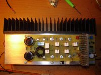
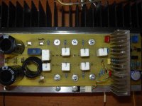
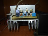
I really like the driver heatsink you used on your modules.
I am curious to know why you chose to place the outpout resister and output inductor seperate from each other rather than the resistor inside the inductor?
I know some like to place the output drivers on a small "L" heatsink backet with for thermal reasons or physical layout reasons. In one of your pics it looks like you have a full PCB width "L" bracket the output devices are mounted on and then that large "L" is mounted to your main heatsink. Then in another pic it looks like your board is mounted in common manner directly to the back of the heatsink. I am curious if the black heatsink of Post #821:
http://www.diyaudio.com/forums/showthread.php?postid=970462#post970462
just happened to be there to hold the ther module stable for pic or while you are working on the module with the uncoated heatsink?
Regards,
John L. Males
Willowdale, Ontario
Canada
29 July 2006 (16:00 -) 16:26
UltimateX86 said:
HI
And to drive 2SC5200 or MJL3281 at +-35V ?
thx
quasi said:
I take it you are considering the transistor output version of this amp. In this case for rails of +/- 35v the MJE340/350 drivers would handle it easily for 8 and 4 ohm loads.
Cheers
quasi,
Would there be less "rail" loss for your BiPolar variant? Soem sense of difference at the +-35V rails and if rail dependant or a fixed loss amount?
I ask as based on yoru MOSFET version you built adn tested the power handing of with your 500VS 53-0-53 I calculated a rail loss of about 17V @ 210W/8Ohms and about 21V @ 360W/4 Ohms. What I am not sure is this calculated loss is actually less in fact and he calculated values are larger than expected due to PSU output limited by the 500VA of the transformer.
I know some time ago you said there were simplier designs I could use for the lower rail voltages I was asking to use with the MOSFET version long before you posted a schematic of your "transistor" (aka BiPolar) vaiant.
I am still biased (pun intended) to building all my amps as MOSFETs. For the lower power designs I coudl use a simpler design like a mini-aleph o similar. I have a preference for all amps to be same with exception of rail voltage geared to a tweeter, midrange or woofer. I might consider the lower rails for the "BiPolar" variant, but I seem to favour using MOSFETs for all amp output devides. The mini-alpehs being Class A will still consume lots of power and still need good heatsinking even for the lower 15-20W ouputs of the mini-alpehs. One of a few reasons I have steered clear of Class A amps.
Regards,
John L. Males
Willowdale, Ontario
Canada
29 July 2006 16:43
- Home
- Amplifiers
- Solid State
- Power amp under development