Hi quasi 
I use UR design but in deferent way the bottom side and
Component side are reversed
Unfortunately I made pcbs in mirror image
Except mje 350/340 and Single turn pots, all components
and power fets are between pcb and heatsink and it look
good 😀
now I am designing high power (10 FET)
stereo version pcb with dc and temp protection,
when I complete I’ll send U Gerber files
I am waiting for U R short cct
Can U help me in (inverse CMMR) please see passive
surround sound thread
🙂 🙂
regards
ravi
Short cct protection
Short cct protection;
The most common short cct protection that I have seen involves using 2 transistors b-e to monitor the voltage across the output stage source (emmitter) resistors. These transistors then shunt the gate drives.
I prefer to disconnect the load permanently until the amp is manually reset.
In my mind there are pros and cons for both.
What I had in mind was an optocoupled sense across the source resistors activating the DC protect cct with a latch that could only be reset by turning the amp off and on.
Any thoughts from our knowledgeable friends?
Elektor made this type of protection circuit in their
100watt amp using a pair 4N35 optoisolators and
BF869 as current monitor
🙂 🙂
cheers
100watt amp using a pair 4N35 optoisolators and
BF869 as current monitor
🙂 🙂
cheers
Hi,
may I suggest a protection circuit that uses n-channel fets to switch the supply to the output stage (while keeping the input and VAS alive in order to recover from failure)?
It has been discussed a couple of times in the solid state and pass labs forums. One would need a "high side" drive (i.e. an elevated supply that could also be used for the input/VAS) and two n-channel mosfets that are capable of withstanding twice the rail voltage at the maximum current and incorporate a very low Rds(on) in order to minimize power loss and heat.
Would work like a solid state relais without the relais contacts (and switching time, sound, arcing, etc.) and require less board space while really switching off the current through both output transistors and speakers. Either ON, ST, IRF and IXYS manufacture suitable mosfets in TO3P/TO247 case (could be mounted and would look like the rest of the output stage).
Note that one would only need one set of power-mosfets per amplifier channel, because when fully on, a single mosfet can sustain (and switch) *a lot* more current than a linear class A/B output stage.
Can anyone report some experience with such an attempt? I remember a couple of DIYers have tried it but I couldn't find the threads right now.
Could work like a charm. 😉
Ciao,
Sebastian.
may I suggest a protection circuit that uses n-channel fets to switch the supply to the output stage (while keeping the input and VAS alive in order to recover from failure)?
It has been discussed a couple of times in the solid state and pass labs forums. One would need a "high side" drive (i.e. an elevated supply that could also be used for the input/VAS) and two n-channel mosfets that are capable of withstanding twice the rail voltage at the maximum current and incorporate a very low Rds(on) in order to minimize power loss and heat.
Would work like a solid state relais without the relais contacts (and switching time, sound, arcing, etc.) and require less board space while really switching off the current through both output transistors and speakers. Either ON, ST, IRF and IXYS manufacture suitable mosfets in TO3P/TO247 case (could be mounted and would look like the rest of the output stage).
Note that one would only need one set of power-mosfets per amplifier channel, because when fully on, a single mosfet can sustain (and switch) *a lot* more current than a linear class A/B output stage.
Can anyone report some experience with such an attempt? I remember a couple of DIYers have tried it but I couldn't find the threads right now.
What I had in mind was an optocoupled sense across the source resistors activating the DC protect cct with a latch that could only be reset by turning the amp off and on.
Could work like a charm. 😉
Ciao,
Sebastian.
STATMENT
Hi! Quasi god job at all , but in your finished pcb's you put DC protection with relay. Where is the PCB with DC protection.I hope you will put on FORUM.!
Hi! Quasi god job at all , but in your finished pcb's you put DC protection with relay. Where is the PCB with DC protection.I hope you will put on FORUM.!
Hi Zeonrider
I posted the shorter board because many people setup thier own DC detection and I thought of posting the cct in a different thread.
Anyway here is the layout that includes this cct;
http://www.diyaudio.com/forums/attachment.php?s=&postid=776114&stamp=1133051396
Cheers
I posted the shorter board because many people setup thier own DC detection and I thought of posting the cct in a different thread.
Anyway here is the layout that includes this cct;
http://www.diyaudio.com/forums/attachment.php?s=&postid=776114&stamp=1133051396
Cheers
Attachments
This is the latest amplifier schematic;
http://www.diyaudio.com/forums/attachment.php?s=&postid=601021&stamp=1111237713
all relevant ccts and layouts are now on this page.
Cheers
http://www.diyaudio.com/forums/attachment.php?s=&postid=601021&stamp=1111237713
all relevant ccts and layouts are now on this page.
Cheers
Hi Quasi,
Can I use 12V relay in DC detect with 12V supply?
I can only get a 12V supply from my transformer for DC detect...
Thanks in advance, and thanks for great schematic I'm building the amp too!!!😀 😀 😀
Chears!!!
Can I use 12V relay in DC detect with 12V supply?
I can only get a 12V supply from my transformer for DC detect...
Thanks in advance, and thanks for great schematic I'm building the amp too!!!😀 😀 😀
Chears!!!
12 volts ?
Yes you can use 12 volts. The relay will take a little longer to switch. If this makes you unhappy you can reduce the value of the 330k resistor or the 470uF capacitor.
Cheers
Yes you can use 12 volts. The relay will take a little longer to switch. If this makes you unhappy you can reduce the value of the 330k resistor or the 470uF capacitor.
Cheers
Replay of Replay
Thanks Quasy, !, and ofcourse what happened with soft start.Because is too many caps.
Thanks Quasy, !, and ofcourse what happened with soft start.Because is too many caps.


ravirat4u said:


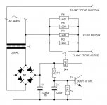
Caution AC!🙂 🙂
This is the slow turn-on cct that I used for the amp. It uses a seperate small transformer to power the delay cct. It's simple (too simple?) and also provides a DC supply for other uses i.e. Fan, LEDs etc.
Cheers

Attachments
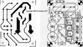
And the tracks ....
That's it. Using all this you should be able to build an amp that is similar to the one I completed.
The amp has just come back from another Hi-Fi nuts house (returned reluctantly after a month) and seems to be going strong.
Good Luck
That's it. Using all this you should be able to build an amp that is similar to the one I completed.
The amp has just come back from another Hi-Fi nuts house (returned reluctantly after a month) and seems to be going strong.
Good Luck
Attachments
Re: 2xreplay of replay
???
can't you see the picture in post #216?
zeonrider said:Nice job, BUT schematic & part list is mising!
???
can't you see the picture in post #216?
- Home
- Amplifiers
- Solid State
- Power amp under development